


Change impact analysis for other safety standards
UM1915
38/43
UM1915 Rev 3
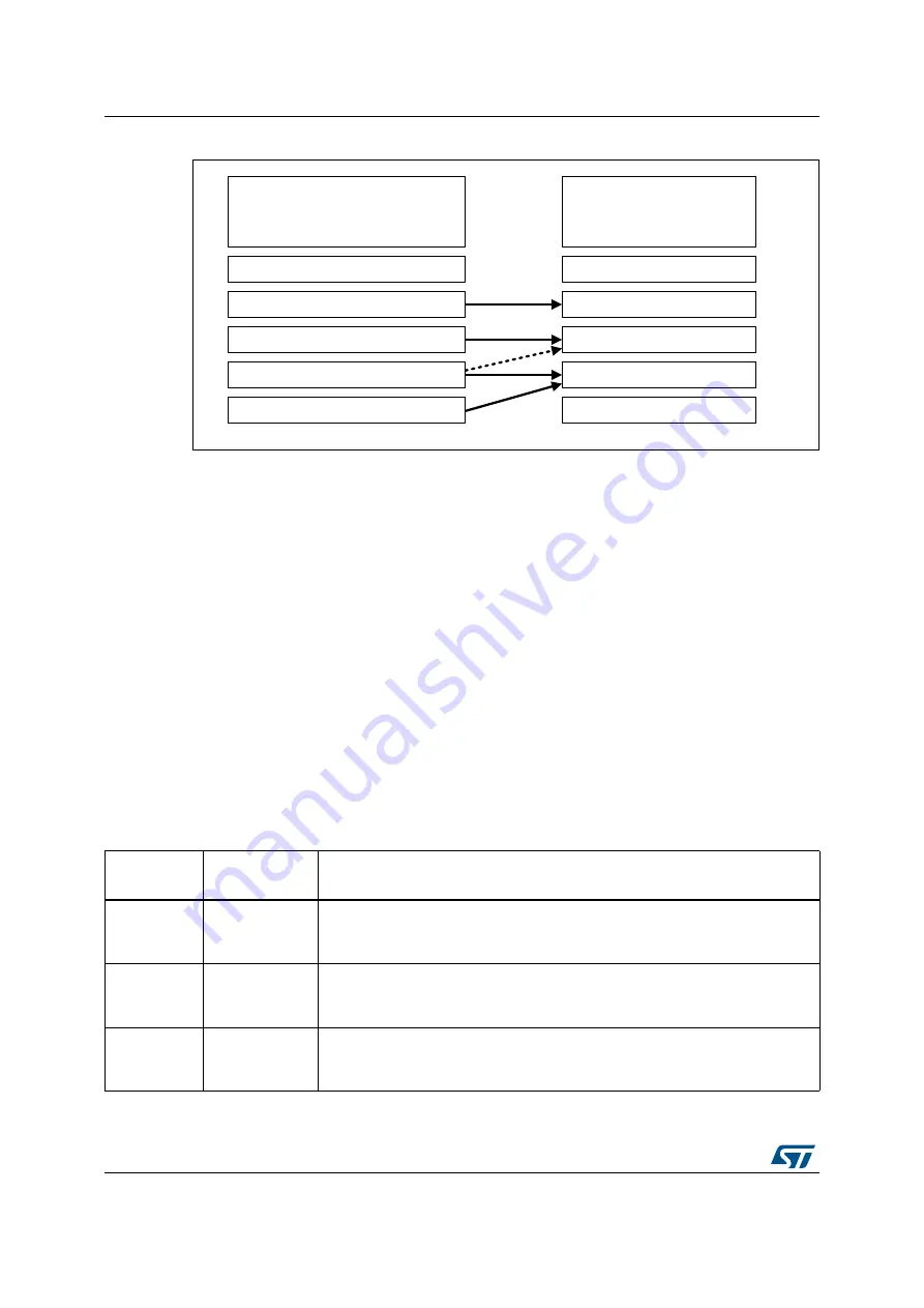
Figure 4. Correlation matrix between SIL and ASIL
In the IEC 61508 scope, end-users can rely on SIL decomposition to define system
architectures where the highest SIL requirements are fulfilled by using lower SILs
redundant sub systems but respecting the requirements in part 2 §7.4.4.2.4. Following the
rules, an SIL3 safety goal can be decomposed leading to an item made of two SIL2
independent elements. Thus, end-users can positively match SEooC assumptions in the
form of STM8AF AoU (refer to
Section 3.7: Assumption of use (AoU)
). Then the safety
requirements of the system under development can integrate the STM8AF MCU together
with the related safety mechanisms defined in this manual, in items performing up to SIL3
safety functions.
A.1.1 Architectural
categories
IEC 61508-6, Annex B requires representing a safety system by means of subsystem block
diagram and representing each subsystem as one or more 1oo1, 1oo2, 2oo2, 1oo2D, 1oo3
or 2oo3 voted groups.
In principle, the safety architectures targeted in this document can be mapped to “1oo1”
or “1oo1d” if HFT = 0 is selected, or “1oo2” or “1oo2d if HFT = 1 if selected (see
069
,(&
6DIHW\,QWHJULW\/HYHO
6,/
,62
$XWRPRWLYH6DIHW\,QWHJULW\/HYHO
$6,/
40
$
%
&
'
Table 6. Some reference architectures for IEC 61508
Architecture
Hardware fault
tolerance (HFT)
Description
1oo1
0
Architecture of a single set of components/ component having no hardware fault
tolerance.
Failure of a unit can lead to a loss of the safety function.
1oo1d
0
Architecture of a single set of components/ component with a diagnostic
section, having no hardware fault tolerance.
Failure of a unit can lead to a loss of the safety function.
1oo2
1
Architecture of two set of components/ component connected in parallel,
having a hardware fault tolerance of 1.
Failure of a unit does not lead to a loss of the safety function.