


D
R
A
F
T
Hardware layout and configuration
UM1461
14/65
Doc ID 022138 Rev 1
Note:
1
Some 0 ohm resistors have to be removed or soldered to enable motor control application
except the solder bridges configurations mentioned above:
– R34, R58 & R51 to be removed
– R66, R204 & R205 to be soldered
2
MicroSD card must be removed from CN6 for motor control application.
2.10 Smartcard
STMicroelectronics smartcard interface chip ST8024 is used on STM3240G-EVAL board for
asynchronous 3V and 5V smartcards. It performs all supply protection and control functions
based on the connections with STM32F407IGH6 listed in
Table 8
:
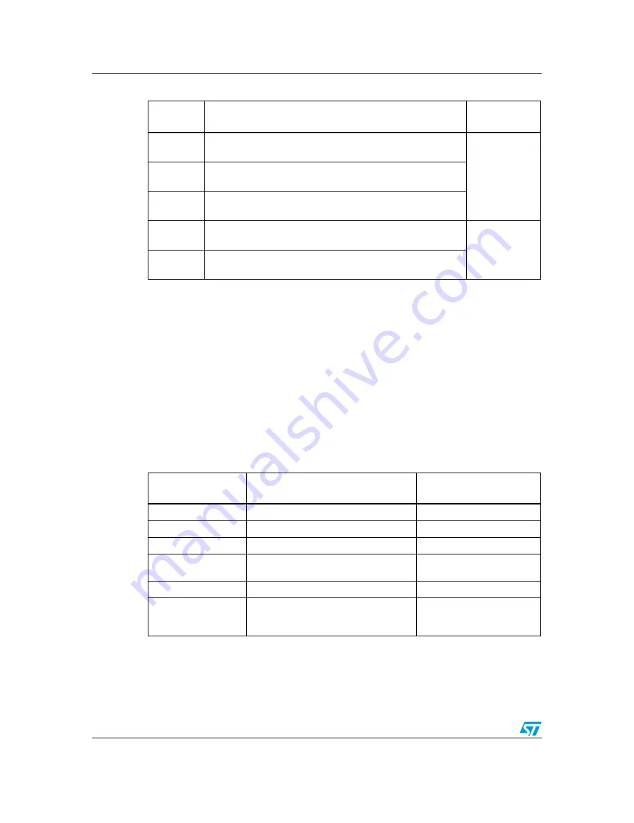
SB10
To connect MC_EnIndex to PB8, close SB10.
Default setting: Open
Ethernet
SB11
To connect MC_CurrentA to PC1, close SB11.
Default setting: Open
SB12
To connect MC_CurrentB to PC2, close SB12.
Default setting: Open
SB14
To connect MC_EnB to PD13, close SB14.
Default setting: Open
FSMC
SB15
To connect MC_EnA to PD12 close SB15.
Default setting: Open
Table 7.
Motor control solder bridges (continued)
Solder
Bridge
Description
Multiplexed
peripherals
Table 8.
Connection between ST8024 and STM32F407IGH6
Signals of ST8024
Description
Connect to
STM32F407IGH6
5V/3V
Smartcard power supply selection pin
PH15
I/OUC
MCU data I/O line
PC6
XTAL1
Crystal or external clock input
PG7
OFF
Detect presence of a card, MCU interrupt,
share same pin with motor controller
PF6
RSTIN
Card reset input from MCU
PF7
CMDVCC
Start activation sequence input (Active
Low), share same pin with I2S DAC and
Motor control
PG12
All manuals and user guides at all-guides.com