3
How to build and run the IO-Link device
3.1
System evaluation setup
can be used as IO-Link Device evaluation system, following the hardware configuration
below.
Step 1.
Maintain the
Close JP4 and JP5 if the Transparent Transmission Mode is selected.
Step 2.
setup, enable the external supply from
to position “E5V”.
Step 3.
–
enable all sensors by closing JP1, JP3, JP11 and JP12
–
JP2 closed on INT1
–
JP4 open
–
JP5 closed on 1V8
–
JP6 closed on 5-6
–
JP7 closed 1-2 and 3-4
–
JP8 closed 1-2 and 3-4
–
JP9 closed on DRDY
–
JP10 closed on INT
Step 4.
expansion board and
development board through the Arduino connectors.
Note:
Connect the boards as shown in
, leaving the two user buttons (the blue and the black ones) out.
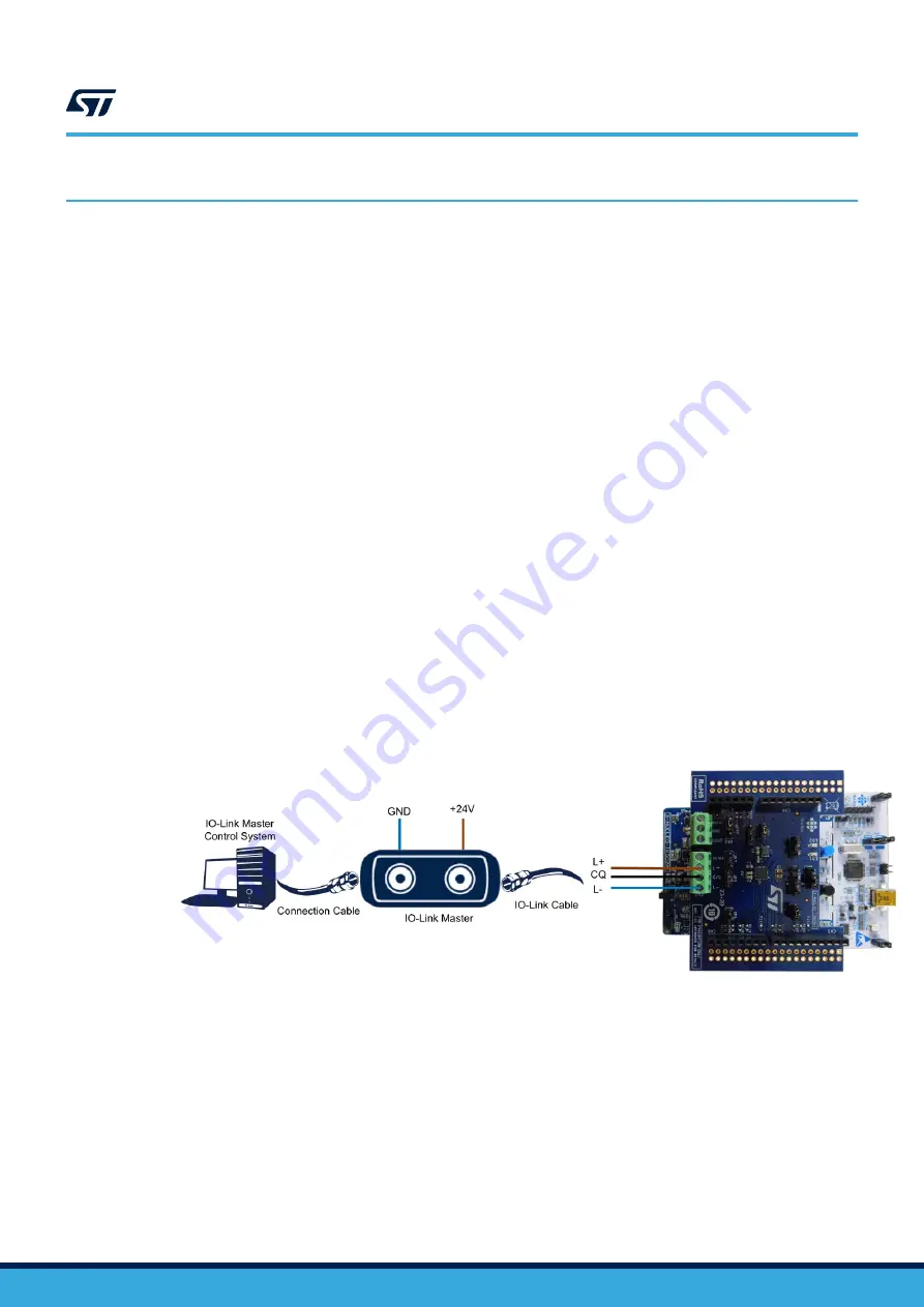
Step 5.
to the IO-Link Master by screwing cables on the CN1 connector,
taking care of the pin/signal correspondence.
Figure 3.
P-NUCLEO-IOD02A1 connections to the IO-Link Master
Step 6.
) in the laptop/PC where
the control tool of your master is running. Depending on the control system of your master, it could be
required that you launch the control tool first and then load the IODD file.
The system is ready to operate: the IO-Link master control tool allows the user to supply, configure
and activate the data transfer (in SIO or IO-Link mode) with the IO-Link device. If the master is the
, refer to its user manual (UM2421 on www.st.com) for the detailed procedure to
use the related control tool.
3.2
System development setup
You can use the
evaluation pack as a development platform for an IO-Link device sensor
node, but with a different firmware managing the sensors.
UM2782
How to build and run the IO-Link device
UM2782
-
Rev 1
page 4/10


