1
Architecture overview
A generic IO-Link system is composed of an IO-Link Master and an IO-Link Device connected by an unshielded
cable. Normally, the IO-Link Master is the connection point between the IO-Link Device and the automation
system.
The IO-Link Master is installed in the control cabinet or, as a remote I/O, directly in the field. It can have
several IO-Link ports (channels): an IO-Link Device can be connected to each port, hence, it is a point-to-point
communication and not a field-bus.
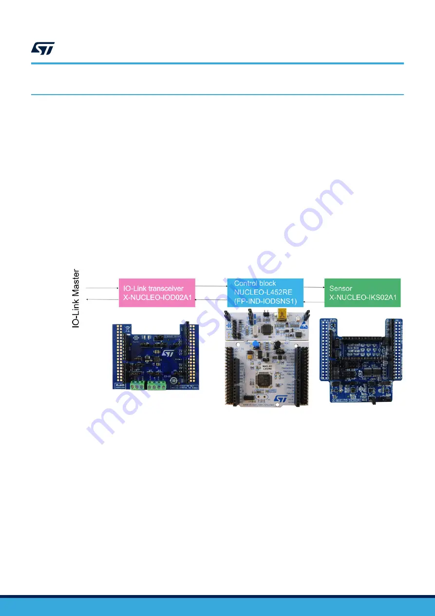
An IO-Link Device, as the
, can be basically schematized as the arrangement of three main
blocks (see
):
•
Control sub-system
board runs the
control software, the IO-Link
demo stack and sensors firmware, accepting the commands and configuration parameters from the IO-Link
master. It also provides all digital signals to perform the proper control of the whole IO-Link device system.
•
IO-Link physical
transceiver, which interfaces the
microcontroller and the IO-Link Master with the IO-Link interface (connectors CN1 and CN2).
•
Sensor
multi-sensor shield, with on-board MEMS 3D acceler 3D
), MEMS 3D magnetometer (
), MEMS 3D accelerometer low power
) and MEMS digital omnidirectional microphone (
).
Figure 2.
P-NUCLEO-IOD02A1 block details
UM2782
Architecture overview
UM2782
-
Rev 1
page 2/10


