VL53L1 breakout board
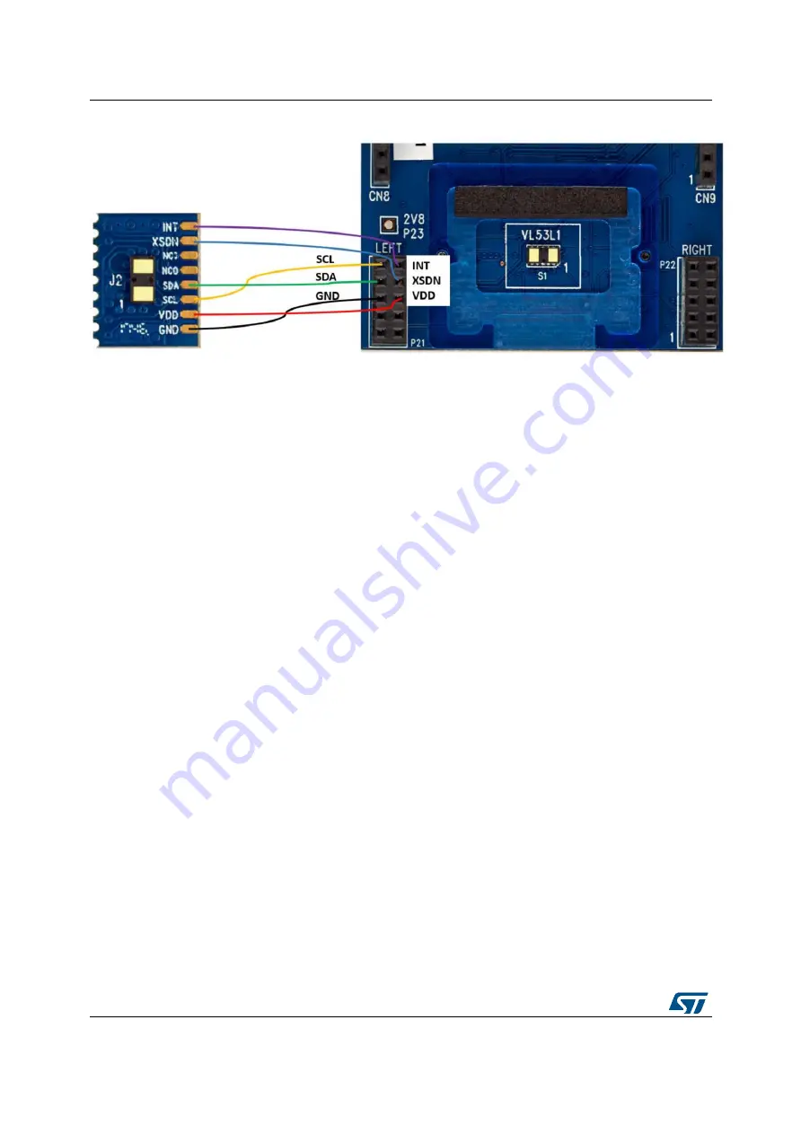
Figure 8. VL53L1 mini PCB flying lead connection to X-NUCLEO-53L1A2 expansion board
14/17
Page 1: ...is based on the ST patented FlightSense technology To allow the user to validate the VL53L1 in an environment as close as possible to its final application the X NUCLEO 53L1A2 expansion board is deliv...
Page 2: ...ew 4 3 2 Electrical schematic and list of materials 8 3 2 1 Electrical schematic 8 3 2 2 List of materials 9 3 3 Solder drop configurations 10 3 4 Integrated device pinning 12 4 VL53L1 breakout board...
Page 3: ...inal product Two VL53L1 breakout boards which can be plugged onto the X NUCLEO 53L1A2 expansion board or connected through flying wires to the X NUCLEO 53L1A2 expansion board Two 10 pin connectors to...
Page 4: ...UCLEO 53L1A2 expansion board VL53L1 VL53L1 VL53L1 3 1 Overview The board allows the user to test the VL53L1 functionality to program it and to understand how to develop an application using the VL53L1...
Page 5: ...ble on www st com The X NUCLEO 53L1A2 expansion board and STM32 Nucleo development board are connected through the Arduino UNO R3 connectors CN5 CN6 CN8 and CN9 as shown in Figure 3 and as described i...
Page 6: ...board soldered device 4 NC PB0 Not used GPIO1 5 INT PC1 1 By default not used interrupt signal from VL53L1 on board soldered device 6 NC PC0 Not used 1 Depends on STM32 Nucleo board solder bridges se...
Page 7: ...eft breakout board 1 CN9 digital 8 NC PA8 Not used 7 NC PB10 6 NC PB4 GPIO1_R 5 INT_R PB5 By default not used interrupt signal from optional VL53L1 right breakout board 1 4 NC PB3 Not used GPIO1_R 3 I...
Page 8: ...3L1A2 expansion board 3 2 Electrical schematic and list of materials 3 2 1 Electrical schematic Figure 4 X NUCLEO 53L1A2 expansion board schematic VL53L1 9 53 1 VL53L1 application VL53L1 CanbeNCorgrou...
Page 9: ...ull up R23 47 k Right breakout board interrupt output pull up 2 8 V regulator application C8 10 F X5R 6 3 V Output voltage decoupling C9 10 F X5R 6 3 V Input voltage decoupling R35 49 9 k Feedback res...
Page 10: ...14 fitted of the Arduino connector conflict on the I2C addresses the addresses of the STMPE1600 can be modified the default addresses A2 A1 A0 000 and 001 If the developer wants to connect breakout bo...
Page 11: ...X NUCLE0 53L1A2 expansion board Figure 5 Interrupt configurations GPI01 configuration GPI01 L and GPI01 R shared with GPI01 11 17...
Page 12: ...X NUCLEO 53L1A2 expansion board 3 4 Integrated device pinning Figure 6 Integrated device pinning 12 17...
Page 13: ...t board VL53L1 mini PCB VL53L1 The VL53L1 breakout boards can be directly plugged onto the X NUCLEO 53L1A2 expansion board through the two 10 pin connectors or connected to the board through flying le...
Page 14: ...VL53L1 breakout board Figure 8 VL53L1 mini PCB flying lead connection to X NUCLEO 53L1A2 expansion board 14 17...
Page 15: ...ry The laser output is designed to remain within Class 1 laser safety limits under all reasonably foreseeable conditions including single faults in compliance with the IEC 60825 1 2014 third edition T...
Page 16: ...Revision history 6 Revision history Table 6 Document revision history Date Revision Changes 01 07 2020 1 Initial release 16 17...
Page 17: ...sponsible for the choice selection and use of ST products and ST assumes no liability for application assistance or the design of Purchasers products No license express or implied to any intellectual...