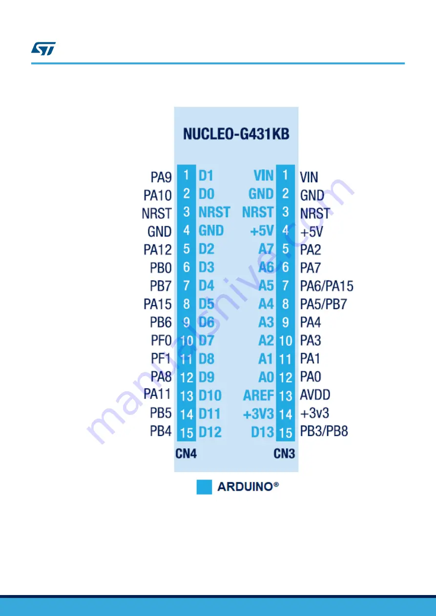
Figure 12.
ARDUINO
®
connector pinout
UM2397
ARDUINO® Nano V3 connectors
-
Rev 2
page 21/30
Page 1: ...open development platform with a wide choice of specialized shields The STM32G4 Nucleo 32 board does not require any separate probe as it integrates the STLINK V3E debugger programmer The STM32G4 Nuc...
Page 2: ...DUINO Nano V3 expansion connector Flexible power supply options ST LINK USB VBUS or external sources On board STLINK V3E debugger programmer with SWD connector USB re enumeration capability virtual CO...
Page 3: ...mation paragraph at the www st com website Next to the evaluation tool ordering part number that is stuck or silk screen printed on the board This board features a specific STM32 device version which...
Page 4: ...s Keil MDK ARM see note IAR EWARM see note GCC based IDEs Note On Windows only 3 3 Demonstration software The demonstration software included in the STM32Cube MCU Package corresponding to the on board...
Page 5: ...tion Jumper JPx ON Jumper fitted Jumper JPx OFF Jumper not fitted Jumper JPx 1 2 Jumper should be fitted between Pin 1 and Pin 2 Solder bridge SBx ON SBx connections closed by 0 resistor Solder bridge...
Page 6: ...s from the host PC and before connecting the board install the Nucleo USB driver available on the www st com stm32nucleo website 3 To power the board connect the STM32G4 Nucleo 32 board to a PC with a...
Page 7: ...eatures on the STM32G4 Nucleo 32 board The mechanical dimensions of the board are shown in Figure 6 Figure 3 Hardware block diagram Connector or jumper STLINK V3E Part STM32G431KB SWD VCP UART GPIOs G...
Page 8: ...T6 CN1 STLINK V3E Micro B USB connector CN2 SWD connector not fitted LD2 green LED USER LD4 green LED 5V_PWR B1 green RESET button LD1 bicolor LED COM X1 25 MHz oscillator X2 24 MHz HSE crystal LD3 re...
Page 9: ...5 U7 5V_USB_STLK regulator STMPS2151STR CN4 ARDUINO Nano connector JP1 1 27 mm jumper for IDD measurement HW2 1 27 mm jumper fitted on JP1 1 2 CN3 ARDUINO Nano connector U6 3V3_STLK regulator LD3985M3...
Page 10: ...6 2 Mechanical drawing Figure 6 STM32G4 Nucleo 32 board mechanical drawing in millimeter 18 542 mm 50 292 mm UM2397 Mechanical drawing UM2397 Rev 2 page 10 30...
Page 11: ...Nucleo 32 board to a Windows PC via USB the user must install a driver for the STLINK V3E not required for Windows 10 It is available at the www st com website In case the STM32G4 Nucleo 32 board is c...
Page 12: ...connector CN1 ARDUINO Nano Connector STM32F723IEK STLINK V3E and bicolor LED LD1 COM DFU connector CN2 MCU STM32G4 LDO LD39050PU33R 3V3 5V U9 U7 LDO LD3985M33R U6 5V_USB_STLK 5V_VIN LDO LD1117S50TR U...
Page 13: ...red Therefore the green LED LD4 remains turned OFF In this case it is mandatory to use an external power supply Caution If the maximum current consumption of the STM32G4 Nucleo 32 board and its shield...
Page 14: ...If the board needs more than 300 mA current the PC may be damaged or can limit the current supplied Consequently the board is not powered correctly 2 Enumeration requests 300 mA so there is risk that...
Page 15: ...rnal oscillator through the pin PF0 ARDUINO D7 pin 10 of the CN4 connector The configuration must be SB9 and SB10 OFF SB11 OFF and SB8 ON SB13 OFF HSE oscillator configuration The clock is provided by...
Page 16: ...power is available on CN3 pin 4 LD3 USB power fault OC overcurrent LD3 indicates that the board power consumption on USB ST LINK exceeds 500 mA Therefore the user must check the root cause of the ove...
Page 17: ...is connected to STM32G4 I O PB3 SB6 ON and SB7 OFF OFF The green user LED LD2 is connected to STM32G4 I O PB8 SB6 OFF and SB7 ON AGND SB16 ON AGND connected to GND Reserved do not modify OFF AGND not...
Page 18: ...connected to PF1 ARDUINO Nano CN4 pin 11 OFF PF1 OSC_OUT pin not connected to PF1 ARDUINO Nano CN4 pin 11 SB8 ON PF0 OSC_IN pin connected to PF0 ARDUINO Nano CN4 pin 10 OFF PF0 OSC_IN pin not connect...
Page 19: ...tor Pin number Pin name Signal name STLINK V3E MCU pin Function CN1 1 VBUS 5V_USB_CHGR 5 V power 2 DM USB_DEV_HS_CN_N R14 USB diff pair N 3 DP USB_DEV_HS_CN_P R15 USB diff pair P 4 ID 5 GND GND 7 2 AR...
Page 20: ...INO connectors CN4 ARDUINO Nano connector CN3 ARDUINO Nano connector The related pinout for ARDUINO connector appears in Figure 12 and is listed in Table 11 UM2397 ARDUINO Nano V3 connectors UM2397 Re...
Page 21: ...Figure 12 ARDUINO connector pinout UM2397 ARDUINO Nano V3 connectors UM2397 Rev 2 page 21 30...
Page 22: ...T_NRST PG10_NRST RESET 4 GND 3V3 input output 5 D2 ARD_D2 PA12 6 D3 ARD_D3 PB0 PWM TIM3_CH3 7 D4 1 ARD_D4 PB7 TIM4_CH2 I2C1_SDA 8 D5 1 ARD_D5 PA15 TIM2_CH1 I2C1_SCL 9 D6 ARD_D6 PB6 PWM TIM1_CH1 10 D7...
Page 23: ...ARD_A5 DC2_IN3 12 PA7 PA7 Analog input ARD_A6 DC2_IN4 13 PB0 PB0 ARD_D3 PWM TIM3_CH3 14 VSSA VSSA Analog Ground 15 VDDA VDDA Analog voltage supply 16 VSS VSS Ground 17 VDD VDD VDD voltage supply 18 P...
Page 24: ...ccordance with the instruction may cause harmful interference to radio communications However there is no guarantee that interference will not occur in a particular installation If this equipment does...
Page 25: ...Revision history Table 13 Document revision history Date Version Changes 17 May 2019 1 Initial release 04 Sep 2019 2 Updated Table 9 and ARDUINO registered trademark UM2397 UM2397 Rev 2 page 25 30...
Page 26: ...Mechanical drawing 9 6 3 Embedded STLINK V3E 11 6 3 1 Drivers 11 6 3 2 STLINK V3E firmware upgrade 11 6 4 Power supply 11 6 4 1 Debugging while using VIN or EXT as an external power supply 14 6 5 Cloc...
Page 27: ...ommunications Commission FCC and Industry Canada IC Compliance Statements 24 9 1 FCC Compliance Statement 24 9 2 IC Compliance Statement 24 Revision history 25 Contents 26 List of tables 28 List of fi...
Page 28: ...rces VIN 7 V 12 V 13 Table 6 External power sources 3V3 13 Table 7 External power sources 5V 14 Table 8 USART2 connection 16 Table 9 Solder bridge configuration 17 Table 10 USB Micro B connector CN1 p...
Page 29: ...re 6 STM32G4 Nucleo 32 board mechanical drawing in millimeter 10 Figure 7 USB composite device 11 Figure 8 STM32G4 Nucleo 32 board power tree 12 Figure 9 STM32G431KB Nucleo 32 board clock configuratio...
Page 30: ...ts and ST assumes no liability for application assistance or the design of Purchasers products No license express or implied to any intellectual property right is granted by ST herein Resale of ST pro...