


UM1509
Configuration
Doc ID 022703 Rev 2
Caution:
Do not fit the jumpers when the U10 RS-232 transceiver is soldered on the evaluation
board.
4.5 Power
supply
There are two options to supply the EVALSP320SPLC evaluation board:
1.
Connecting the +5 V voltage adapter (delivered in the EVALSP320SPLC package) to
the J11 power voltage connector on the CPU board.
2.
Connecting a 7 V to 30 V DC power source (not included in the EVALSP320SPLC
package) to either connectors CN17 or CN18 on the application board.
The input voltage is connected to the DC/DC converter U16 (L7986A or optionally L5973A).
The board is protected against overvoltages by the D4 transil diode (SM6T33A) and against
possible reverse polarity voltage from an incorrect power plug-in by the D3 Schottky diode
(STPS3L40U).
Warning:
Do not use both Power supply options at the same time.
Doing this may destroy the boards.
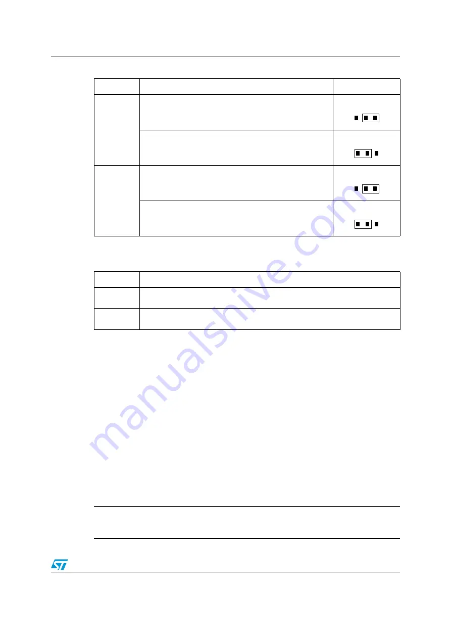
JP12
(SMD
resistor)
(1)
UART2_TX line is connected to the RS-485 transceiver U11.
UART2_TX line is connected to the RS-232 transceiver U13
(Default).
JP13
(SMD
resistor)
UART2_RX line is connected to the RS-485 transceiver U11.
UART2_RX line is connected to the RS-232 transceiver U13
(Default).
1.
The configuration of this JP is done loading a 0 ohm resistance between two different positions.
Table 7.
UART0/RS-232 transceiver signals from the CPU board
Jumper
Description
JP17
Connects the RS232_TXD signal of the CPU board RS-232 transceiver to CN13
(UART0) Default setting: Not loaded
JP18
Connects the RS232_RXD signal of the CPU board RS-232 transceiver to CN13
(UART0) Default setting: Not loaded
Table 6.
UART2 RS-232/RS-485 configuration (continued)
Jumper
Description
Configuration
1 2 3
1 2 3
1 2 3
1 2 3