background image


November 2017 

DocID030935 Rev 1 

1/16 


www.st.com


TN1250 

Technical note 

Press-

fit ACEPACK™ power modules mounting instructions 


Introduction 

ST introduces the ACEPACK™ Power Module family, designed for easy mounting and reliable 
performance in rugged applications. The available module form facto

rs are ACEPACK™ 1 with 33.8 mm 

x 48 

mm and ACEPACK™ 2 with 56.7 mm x 48 mm body dimensions. Various die selections in silicon 

and silicon carbide substrates can be housed in several configurations. 

These modules feature a compact, fully isolated, low profile housing able to integrate very high power 
density components in a low junction-to-case thermal resistance DBC. Power modules simplify the 
design and increase reliability, while PCB size and system costs are optimized. 

The following sections provide recommendations for the connection of these modules to a printed circuit 
board (PCB) and mounting and dismounting methods to achieve adequate connections, reliability and 
performance in typical applications. 

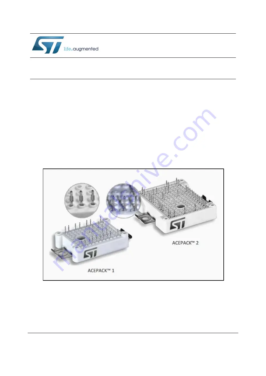
Figure 1

: ACEPACK™ 1 and ACEPACK™ 2 


Summary of Contents for A2F12M12W2-F1

Page 1: ... and silicon carbide substrates can be housed in several configurations These modules feature a compact fully isolated low profile housing able to integrate very high power density components in a low junction to case thermal resistance DBC Power modules simplify the design and increase reliability while PCB size and system costs are optimized The following sections provide recommendations for the...

Page 2: ... in process 5 2 2 Multiple modules press in process 6 3 Fixing a PCB to the ACEPACK module 8 4 Mounting the module to a heat sink 9 4 1 Requirements for a heat sink 9 4 2 Application of thermal paste 9 4 3 Heatsink mounting 9 5 Assembly of the PCB and heat sink 12 6 Clearance and creepage distances 14 7 Revision history 15 ...

Page 3: ...mage to the pins and the PTH If the finished hole diameter is too large it may not form a reliable connection with the pin The initial hole diameter prior to plating is important in determining the reliability of press fit connections As per IEC 60352 5 specification it should be 1 15 mm typical The thickness of the copper plating applied to the initial hole shall be minimum 25 μm to maximum 50 μm...

Page 4: ...tended to accommodate the tolerance and provides the basis for the cold welding The resulting forces during the press fit process ensure that the welded materials on the PCB and pin exhibit a continuously consistent and unlike other contact technologies very small electrical contact resistance see Figure 3 Materials connected together in a gas tight manner due to the press in force Figure 3 Materi...

Page 5: ...bility of the press fit connection the travel distance during the press in process should be controlled to ensure that the press fit zone of the pins sits properly in the plated through hole the speed influences the quality of the press fit connection The speed should not be lower than 25 mm min according to IEC 60352 5 A lower speed can lead to increased press in forces and deformation of the pin...

Page 6: ...ts 2 2 Multiple modules press in process When multiple modules are assembled on the same PCB and the same heat sink the height tolerances among the modules must be minimized to guarantee adequate contact on the heatsink and avoid mechanical stress on the PCB In this case a press in tool with distance keepers is required to ensure the same distance between PCB and the top of the modules as shown in...

Page 7: ...nents should be designed so that no contact among them can occur during the press in process The module and the PCB are first placed on the lower press in tool and the module is then aligned to the PCB with the guide pins Then the upper press in tool can start moving down the module until the distance keepers touch the surface of the PCB ...

Page 8: ...w excluding the PCB thickness should be 4 0 8 0 mm Screwdriver speed lower than 300 rpm and screwdriver torque 0 4 Nm 10 is recommended Screwing into a plastic cavity is a delicate operation and care has to be taken to avoid stand off damage We suggest using M2 5 x L self tapping screws with length L depending on the PCB thickness stand off thread has to be between 4 and 8 mm The screws will self ...

Page 9: ... sink In order to maximize heat transfer efficiency the heat sink contact surface must be flat and clean The required heat sink surface qualities to achieve good thermal conductivity must be according to DIN 4768 1 Roughness Rz should be 10 μm or less and flatness based on a length of 100 mm should be 50 μm or less In particular the flatness must be less than above value in the module mounting are...

Page 10: ... to avoid tilting on one side of module It is recommended to synchronize the two electric screwdrivers with the same rpm and maximum torque In the three step method 1 fasten the first screw only until it touches the screw clamp and does not provoke tilting of the module 2 fasten the second screw to the final torque see Table 3 Technical data of the mounting screw 3 fasten the first screw to full t...

Page 11: ... the module to a heat sink DocID030935 Rev 1 11 16 Figure 11 Module to heatsink fastening method Table 3 Technical data of the mounting screw Description Value Mounting screw M4 Recommended mounting tourque 2 0 2 3 Nm ...

Page 12: ...ht tolerance between modules can result in the mechanical stresses on the board and modules To reduce stress space posts should be added on the heat sink to prevent movement of the PCB The recommended height of the space posts is 12 4 0 0 1 mm The effective distance between center of stand off and the space post X is 50 mm minimum as shown in the following figure Figure 12 Assembly procedure when ...

Page 13: ...TN1250 Assembly of the PCB and heat sink DocID030935 Rev 1 13 16 Figure 13 Heat sink mounting ...

Page 14: ...d or additional isolation measures like lacquering must be taken Figure 14 Air path between clip and PCB The minimum clearance distance between the screw and the PCB depends on the screw itself The distance is 6 8 mm with a hexagon socket head screw according to DIN 912 a washer according to DIN 125 and the clamp see Figure 14 Air path between clip and PCB The clearance and creepage distances spec...

Page 15: ...TN1250 Revision history DocID030935 Rev 1 15 16 7 Revision history Table 4 Document revision history Date Revision Changes 07 Nov 2017 1 Initial release ...

Page 16: ...asers are solely responsible for the choice selection and use of ST products and ST assumes no liability for application assistance or the design of Purchasers products No license express or implied to any intellectual property right is granted by ST herein Resale of ST products with provisions different from the information set forth herein shall void any warranty granted by ST for such product S...

Reviews: