


29
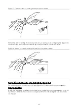
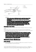
Figure 13. Suture the lead
1.
Vein
2.
Fascia
3.
Lead body
CAUTION:
Use the suture sleeve to distribute the tension created by the suture. Failure
to use the suture sleeve may result in damage to the lead's insulation or
conductor coil.
Do not slide the suture sleeve over the electrode rings. Suture sleeve sticking
can occur. If this occurs, carefully twist the sleeve off the ring toward the
connector pin; pulling the suture sleeve when it is positioned over the
electrode ring may cause a tear in the lead body near the electrode ring.
Do not tie the suture around the suture sleeve and lead too tightly, as this
may result in excessive stress applied to the lead body.
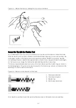
Connection to the Device
Once the lead is anchored, connect the lead to the device following the instructions in the device
manual.
Grasp the lead connector as close as possible to the connector pin while inserting the lead
connector straight into the device port. If necessary, regrip the lead and continue to insert the lead
connector until it is fully seated in the device port.
CAUTION: Orient the excess lead length and the device to minimize the potential
for insulation damage resulting from lead-to-lead or device-to-lead interaction. For
example, minimize the potential for leads lying on top of each other under the
device and ensure that there are no sharp bends in the lead. Lead insulation
damage can create an alternate electrical current path which may result in
compromised therapy delivery. Current practice indicates that a subcutaneous
pocket is preferred over a subpectoral pocket
.
Maintaining Device Effectiveness
Device Storage
The lead should be stored at room temperature between 20°C-25°C (68°F-77°F). Excursions
are permitted between 15°C-40°C (59°F-104°F).
7
Furman S, Hayes DL, Holmes DR. A Practice of Cardiac Pacing. 3rd ed. New York: Futura Publishing, Inc.; 1993:286-289.
8
Belott, PH, Reynolds, DW. Permanent Pacemaker and Implantable Cardioverter-Defibrillator Implantation. In: Ellenbogen KA, Kay
GN, Wilkoff BL, eds. Clinical Cardiac Pacing and Defibrillation. 2nd ed. Philadelphia, Pa: WB Saunders; 1995:613-615.
Summary of Contents for Tendril MRI LPA1200M
Page 1: ...Tendril MRI Pacing leads Model LPA1200M User s Manual ...
Page 13: ...11 Figure 1 Lead Safety Phase The figure below depicts the MRI Phase ...
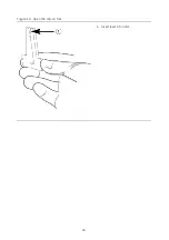
Page 28: ...26 Figure 10 Open the clip on tool 1 Insert lead into notch ...
Page 35: ......
Page 36: ......
Page 37: ......


