5136-DNP-PCI
Hardware Reference
© 1999 SST/Woodhead Canada Limited
13
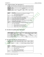
PCI CFG
Register
Address
Register Function
32 24 23 16 15 8 7
0
PCI
Writable
0x2C
Subsystem ID
0x0010
Subsystem Vendor ID
0x133D
N
0x30
PCI Base Address for Local Expansion ROM
0x00000000
Y
0x34
Reserved
0x00000000
N
0x38
Reserved
0x00000000
N
0x3C
Max_Lat
0x00
Min_Gnt
0x00
Interrupt Pin
0x01
Interrupt Line
0x00
Y[7:0]
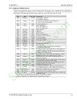
4.5 Application Module Header
Applications for the 5136-DNP-PCI card are based on an event-driven kernel. This kernel provides an abstract
hardware interface, startup self-diagnostics and common services such as timers and event management.
The kernel reserves the first 128 bytes of the host interface block for loader interface and run-time status
information common to all 5136-DNP-PCI applications. This area is called the Application Module Header.
4.5.1 Data Type Descriptions
Data Type
Description
CHAR
8-bit ASCII character, 1 byte
UINT1
unsigned integer, 1 byte
SINT1
signed integer, 1 byte
UINT2
unsigned integer, 2 bytes
SINT2
signed integer, 2 bytes
UINT4
unsigned integer, 4 bytes
4.5.2 Byte Ordering
The 5136-DNP-PCI interface card uses Intel style byte ordering for multi-byte entities LSB-low address and MSB-
high address. If your host system uses Motorola byte ordering (MSB-low address and LSB-high address) you must
compensate for byte ordering in software.
The following macro will compensate for byte ordering in a 16-bit data entity.
#define SWAP_WORD (WordData) ((WordData<<8) | (WordData>>8))
StockCheck.com


