

1
1
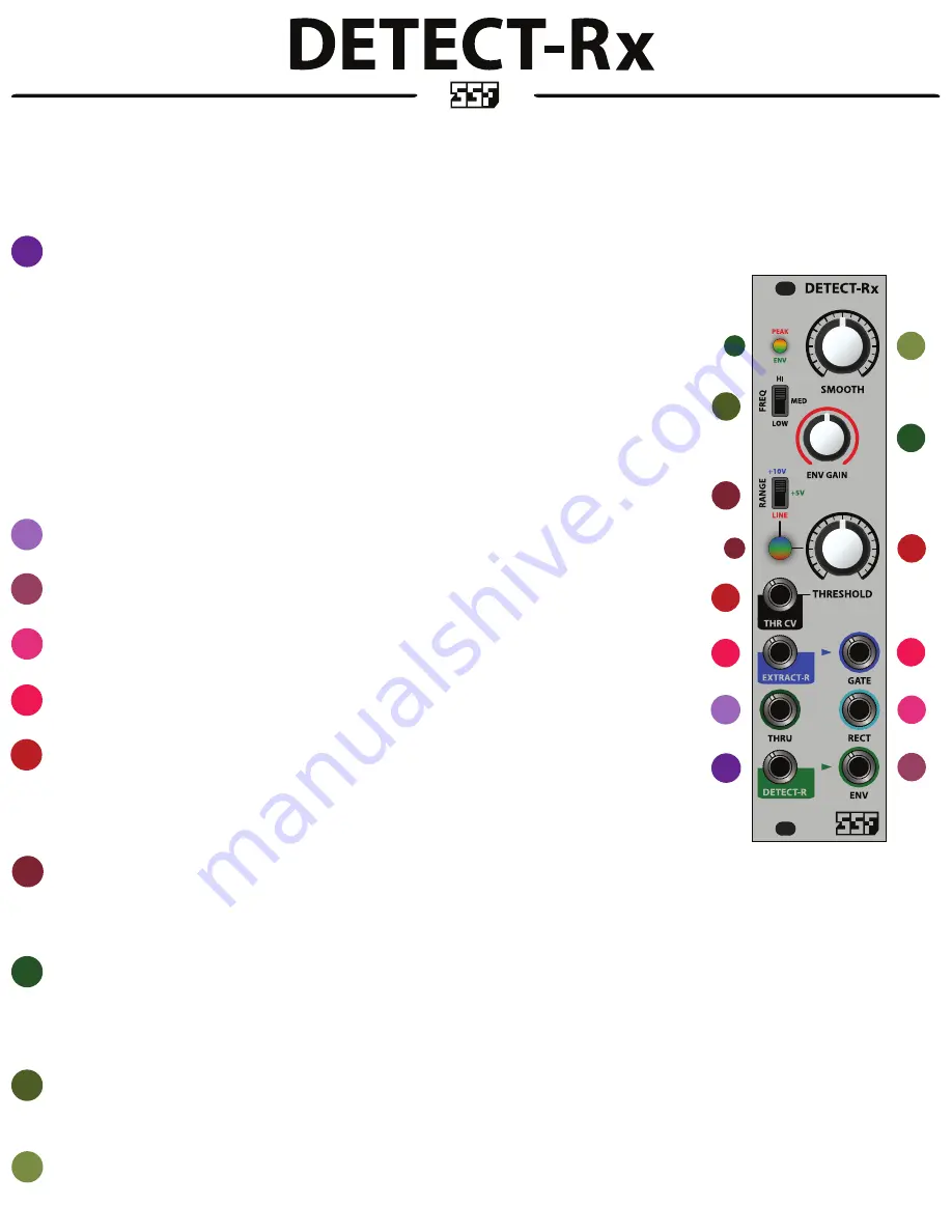
DETECT-R INPUT and NORMALIZATION
This is the input to the DETECT-R, a versatile envelope follower. The DETECT-R will transform signals into time varying control voltages that follow the
amplitude level of the input signal. Controls for the DETECT-R are explained in sections 8-10, below.
The input signal is buffered to the THRU output (section 2) for routing to another module without the need for a multiple. For example, patch a dynamic
mix into the DETECT-R, THRU out to a VCF’s signal input, and ENV out to the VCF’s CV input.
The DETECT-R input is also the input to the rectification circuit (RECT, section 4).
NORMALIZATION
:
In addition to the direct routing scheme explained above, the DETECT-R input will route to the gate EXTRACT-R when nothing is patched into the EXTRACT-R
input. This allows for all DETECT-Rx functions to be used simultaneously from a single signal input. Otherwise, the DETECT-R and EXTRACT-R may be used
exclusively.
Similarly, the GATE output is normalized into the DETECT-R input when nothing is patched into the DETECT-R. The normalized gate signal routes into the
DETECT-R to provide a simultaneous GATE and
gated envelope
out. The envelope shape is affected by the EXTRACT-R controls as well as the gate length,
which is adjustable via the THRESHOLD control.
2
2
THRU
Provides a buffered copy of the signal applied to the DETECT-R input.
3
3
ENVELOPE OUTPUT
This is the DETECT-R’s envelope follower output.
4
4
RECTIFIER OUTPUT
All signals patched into the DETECT-R are rectified and sent to the RECT output jack.
5
5
GATE EXTRACT-R
INPUT and OUTPUT of the threshold based gate extractor. See section 1, above for normalization scheme when solely using the EXTRACT-R input.
6
THRESHOLD and THR CV
The knob controls the voltage threshold level. At minimum, the gate will fire for all signals above 0V (zero volts). At maximum, the gate will fire at the voltage
level determined by the RANGE switch, described in section 7, below.
A control voltage may be used as a dynamic threshold control when patched into the THR CV input. The knob controls the CV depth when CV is applied to this
input.
7
7
EXTRACT-R RANGE SWITCH and LED
The RANGE switch provides three common levels that set the maximum span of the threshold control.
10V - best when extracting gates from external envelopes and louder signals - BLUE LED
5V - typical range for extracting gates from common modular audio signal levels - GREEN LED
LINE - for consumer line level instruments such as synthesizers, desktop boxes and effects. Can also accommodate louder guitar pick-ups. Some gain staging may be necessary for lower level instruments - RED LED
7
8
8
8
ENV LEVEL CONTROL and LED
Controls the gain of the output ENV of the DETECT-R. Largely dependent on the signal level applied to the DETECT-R input, this control will accommodate just about any signal level. Signals can be both attenuated and
amplified using this control. You may choose to use this control in conjunction with external CV input attenuators, or as the sole envelope CV depth control.
The LED indicates an active envelope shown in GREEN. The envelope peak is indicated in ORANGE - this indicates that the envelope has reached it’s clipping level. Peaking is not a bad thing unless the LED is constantly
ORANGE - which indicates that the signal is constantly at maximum level - this will result in very little dynamic content but will not do any harm.
9
9
FREQUENCY RANGE SWITCH
One of the most useful features of the DETECT-Rx, the FREQ range switch allows you to select three frequency bands that the envelope follower will sense from the input signal and create dynamic transients that follow
the selected frequency band. In general, HI produces fast transients as it follows the high frequency content of a signal, MED is a bit slower as it follows the mid bands and LOW produces longer transients as it follows
the low bands and overall emphasis of the input signal.
10
SYNOPSIS
DETECT-Rx
offers three useful synthesizer functions including a versatile envelope follower (DETECT-R), voltage controlled gate extractor (EXTRACT-R) and signal rectifier (RECT).
The
DETECT-R
provides advanced features compared to typical envelope followers with the addition of a detection frequency select switch, manual smoothing filter and attenuation/gain control.
The
EXTRACT-R
provides both manual and CV attenuated control over signal threshold levels for gate extraction. Three selectable signal ranges are available to accommodate all signal types, including line level signals.
RECT
is a positively rectified signal output that will also accommodate all signal levels. Rectification is useful for both CV and audio. You can turn bipolar signals into positive signals or create octave up effects and 2nd
harmonic distortion among other uses.
Please read the manual carefully to understand the module functions and get the best use out of the
DETECT-Rx
.
5
6
6
10
SMOOTH
This manual smoothing filter adds an additional transient shaping function to the DETECT-R envelope follower circuitry. Essentially a low pass filter that scales appropriately to the selected frequency band, this control
can smooth out the ripple commonly associated with envelope followers as well as provide a means for fine tuning the desired envelope output for a wide variety of expressive transient shapes.