


Model SR2555 Stand-On Scale
Rev 991222
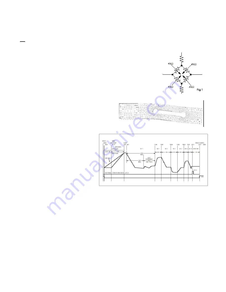
Figure 2. Force Cell bending with applied weight (displacement exaggerated for clarity)
Figure 3. Analog to digital converter timing diagram (from Maxim MAX132 data sheet).
SECTION I
S
S
SR2555 Theory of Operation
1.3
The SR2555 patient weighing system is a digital weigh scale. Four strain-gauge force cells convert the force of a patient’s
weight into an analog signal. This signal is amplified by a chopper-stabilized operational amplifier and converted to a digital signal
by a quad slope analog to digital converter. The digital signal is transferred to a micro-controller where it is filtered, converted to
appropriate units and displayed on a dot-matrix liquid crystal display.
The base of the SR2555 patient weighing system contains four strain gauge based
force cells (Analog board J1..4). Each cell contains four strain gauges mounted in a full
Whetstone-bridge configuration (Figure 1.) These bridges convert the physical bending of the
force cell (Figure 2.), due to the patient’s mass on the system, into minute changes in
electrical resistance. These changes in resistance produce a voltage difference across the
Whetstone Bridge, which is amplified by the chopper-stabilized operational amplifier (Analog
board U1). The amplifier is configured to current sum the output of each cell, with
potentiometers (Analog board R1, R2, R4, R5) serving to adjust the sensitivity (voltage out per
unit of weight applied) of each bridge. The offset potentiometer (Analog board R3) produces
a small current, which nulls the output of the amplifier for a n unloaded system.
The output of the operational amplifier is digitized by the quad
slope analog to digital converter (Analog board U5). The
converter integrates the analog signal onto the integrating
capacitor (Analog board C9) over a short interval. The
integrating capacitor is then discharged at a rate proportional
to the reference voltage applied to the converter
(Analog board C11 and C10). The residual voltage
on the integrating capacitor (Analog board C9) is
then multiplied by a factor of eight and again
discharged at a rate proportional to the reference
voltage (Figure 3.). The residual voltage from this
discharge is again multiplied by eight and again
discharged. The time taken to discharge the
capacitor is proportional to the voltage from the
operational amplifier, which is proportional to the
weight on the force cells. The time is stored as a
binary number in the analog to digital converter
and is transferred to the micro-controller when the
conversion is complete.
The micro-controller (Readout U1)
averages and filters the digital output of the
analog to digital converter, subtracts the value
saved during the system tare operation and scales
the filtered output to the appropriate units (Kg or
Lb.) then displays the result on the dot-matrix liquid crystal display. The micro-controller performs a rolling average of two seconds
of data for continuous weigh and, for AutoHold, the micro-controller averages two seconds of data, minimum, before locking in
on the reading. If the data variance is greater than 0.1% in the AutoHold mode, the micro-controller will reset the filter and start a
new averaging period.
The micro-controller can be placed in a calibration mode (Readout J5), where the system can be re-calibrated. In the
calibration mode, the result of the weigh operation is scaled to match the value entered by the decimal keypad. This new
calibration factor is then stored in the non-volatile memory (Analog board U4).
Page 2