


(Output Setup for Humidity Control continued...)
Sensor Adjustment:
The Sensor Adjustment setting is used to alter the humidity level read by the humidity probe to match other
equipment.
Note: The sensor used in the Herpstat Humidity Probes are typically more accurate than most
other equipment. Adjustments to this setting are usually not necessary initially. However, over time any
humidity sensor can drift and may need to be replaced and should be thought of as a consumable product.
Accuracy can be tested with a Humidipak
®
pouch and then adjust this setting to match the difference
.
RH Swing:
This setting controls the range of humidity before the output is re-enabled after it has made it to the RH% level.
For example:
If the RH% level is set to 80% and the RH Swing is set to 5% the output will be powered until
the humidity level reaches 80%. The output will then shut off and not power back on until the humidity level
has dropped 5% (Swing).
Duration:
Note: Only available in RH Scheduled or RH Hybrid modes.
This setting is the length of time the output will be powered during a humidity session. In Hybrid mode the
power will be shut off if the humidity exceeds the setting in the RH% menu.
Security Passcode
From the initial menu screen select Security Passcode using the Plus and Minus button and press Enter.
This setting creates a 4-digit Passcode that is required to be entered before menu access is granted. Use the
Plus and Minus buttons to toggle the individual digit and the Enter button to advance to the next digit. Entering
all zero's will disable the Passcode. If the menu timeout expires while in this setting the Passcode will be
disabled automatically. If you forget this Passcode in order to regain access to the menu requires the device to
be reset to factory defaults. This can be done by holding down the Plus button while plugging the Herpstat into
power. All settings are lost in the reset process.
Safety Setup
(menu option)
From the initial menu screen select Safety Setup using the Plus and Minus button and press Enter.
Safety:
This setting determines what course of action will take place during an error condition. This also controls the
built in safety relay. Once the error condition is corrected the device will return to normal operations.
Options: IO=INDIVIDUAL OUTPUTS AO=ALL OUTPUTS
INDIVIDUAL OUTPUTS: Excludes High / Low
This option is the default setting and does not enable the built in safety relay. During an error condition it turns
off the output that has the error. High/Low alarms will not shut off the output.
INDIVIDUAL OUTPUTS: Includes High / Low
This option does not enable the built in safety relay. During an error condition it turns off the output that has
the error. High/Low alarms will shut off the output.
ALL OUTPUTS IF: Any Error
This option enables the built in safety relay. If any error condition occurs all outputs will be turned off and the
safety relay is triggered, which cuts the main power to all the outputs.
ALL OUTPUTS IF: High/Low Error
This option enables the built in safety relay. If any High/Low alarm condition is set and is breached all outputs
will be turned off and the safety relay is triggered, which cuts the main power to all the outputs.
ALL OUTPUTS IF: Low Alarm Error
This option enables the built in safety relay. If any Low alarm condition is set and is breached all outputs will be
turned off and the safety relay is triggered, which cuts the main power to all the outputs.
ALL OUTPUTS IF: High Alarm Error
This option enables the built in safety relay. If any High alarm condition is set and is breached all outputs will
be turned off and the safety relay is triggered, which cuts the main power to all the outputs.
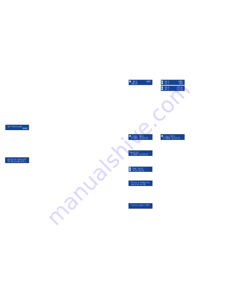
The Display
In normal operation the Minus button will toggle between the available displays while the Plus button will
activate special features of that display. The Enter button will activate the menu system.
Temperature / Humidity Probe Status & Power Output
This display shows the current temperatures and humidity levels from attached probes. It will also indicate if an
output is disabled or set to lighting mode. For each output it will show the amount of power being applied. If
an error occurs a description will be shown instead of the output information. The setting the device is trying to
achieve is in parentheses. When ramping is enabled for temperature the value in parentheses will change
according to the time based curve. The Herpstat 1 combines this on a single display while the Herpstat 2 breaks
this into two displays with the first one indicating the output power and the second indicating the setting it is
trying to achieve.
Special Symbols:
Next to the number of the output an arrow symbol will appear if that output is currently in a ramping session. A
right arrow (
→
) will appear if the ramp is increasing. A left arrow (
←
)
will appear if the ramp is decreasing.
Next to the number of the output a minus sign (
-
) will appear if a Low Alarm has been breached. A plus sign
(
+
) will appear if a High Alarm has been breached.
High Low Status
This display indicates the highest and lowest temperature/humidity level recorded for the probe and the time at
which it was recorded. Pressing the + button will reset the High/Low to the current reading.
System Information
This display indicates the internal clock time and date and the Power Outage Monitor. Each time the Herpstat is
powered on it increments the Power Outage Monitor. To reset the monitor to zero press the + button.
This display indicates the current time schedule each output is adhering to. If the NiteCycle is disabled on the
output it will always show Day Cycle. If an output's mode is set to disabled then it will also show disabled here.
This display will only be available if one of the humidity modes is enabled. If the mode is set to Humidity
Scheduled or Hybrid then pressing the Plus button will schedule a humidity session once the internal clock gets
to the following minute. When the mode is set to Humidity Sensed then pressing the Plus button will power on
the output. This type of forced session has an automatic timeout but should be canceled by the user and not
left unattended. After initiating a forced humidity session pressing the Plus button a second time will end/cancel
the session.
This display will only be available if one of the lighting modes is enabled. If the Plus button is pressed it will
turn on the outputs set to lighting. Pressing the Plus button a second time will return the lights to their previous
state.


