background image


SPIDAR Software 


44 


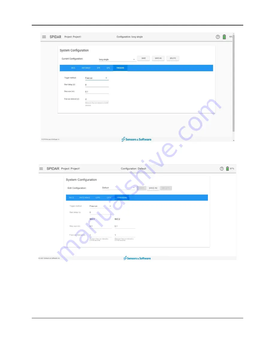
Figure 4-26: Trigger set to Free Run (single NIC-500) 


Figure 4-27: Trigger set to Free Run (multiple NIC-500) 

  Free-run interval 

– the time between GPR traces.   

  Start delay (s) - the user can set an initial time delay in seconds, to allow time to get 

setup and start the survey line.  If there are multiple NIC-500s, the Start Delay must be 
the same for all NIC-500s. 

  Step size 

– set individually per NIC-500, the free-run interval and speed together will be 

used to maintain the desired step size, as per the following equation: 

Summary of Contents for SPIDAR NIC-500s

Page 1: ......

Page 2: ...ii...

Page 3: ...5 or register your product online at www sensoft ca product registration Name Company Name Address City State Province Zip Code Country email Phone Fax Component Serial Numbers refer to packing list o...

Page 4: ...Warranty Confirmation iv...

Page 5: ...ly Do not replace detachable MAINS supply cords for the battery charger AC adapter by inadequately RATED cords The exterior of this product should be cleaned using a damp cloth Safety Symbols Consult...

Page 6: ...vi...

Page 7: ...X 46 4 5 Line Scan 51 4 6 Admin 53 5 SPIDAR SDK 59 5 1 Activating SDK 59 5 2 Configuring the Ethernet connection 63 5 3 Changes in SDK mode 64 5 3 1 Changing the IP Address and Netmask 65 5 3 2 Data C...

Page 8: ...culating GPS Latency 87 Appendix D GPR Knowledge 93 Appendix E Port Specifications 95 Appendix F Health Safety Certification 97 Appendix G GPR Emissions Interference and Regulations 99 Appendix H Inst...

Page 9: ...ultiple NIC 500Ns can be connected together daisy chained to run several Noggins simultaneously NIC 500P used to run pulseEKKO PRO antennas Each NIC 500P can run 2 pairs of pulseEKKO PRO transmitters...

Page 10: ...Introduction 2...

Page 11: ...ftware the operational software that allows the user to setup parameters for data acquisition The user can access this through a web browser such as Google Chrome on their device Storage a hard drive...

Page 12: ...le NIC 500 or the Master NIC 500 in a daisy chained setup the power supply will be plugged into this port If this is a subordinate NIC 500 then the Sync cable will get plugged into this port coming fr...

Page 13: ...gin systems this is called daisy chaining On the long side of the NIC 500 opposite side to the power and odometer connections there are two Noggin ports and a serial port Figure 2 4 described below Se...

Page 14: ...u will find 4 pulseEKKO ports and a serial port Figure 2 5 which are described below Serial port used to connect a GPS receiver The GPS receiver can receive power from this port if power out is enable...

Page 15: ...PRO transmitters and receivers simultaneously The key distinction compared to the NIC 500P is that any combination of transmitters and receivers can be connected to the NIC 500X For example various co...

Page 16: ...eiver can receive power from this port if power out is enabled For more information see Section 3 3 pulseEKKO antenna ports there are eight numbered ports available to connect up to eight pulseEKKO PR...

Page 17: ...able provides power to the NIC 500 One end plugs into the Link In port the other end plugs into the power supply Ethernet Cable required when connecting two NIC 500s together The ends connect to the E...

Page 18: ...system Odometer Determine if an odometer will be used to trigger the system from a SmartCart for example If so connect the odometer cable to the odometer port on the NIC 500 Figure 3 3 Ethernet If a...

Page 19: ...IC 500N Up to two Noggin systems can be plugged into the Noggin ports on a single NIC 500 The ports are numbered 1 and 2 If you are running one Noggin plug it into Port 1 on the NIC 500 Plug the 37 pi...

Page 20: ...re numbered 1 2 3 and 4 Note that ports 1 and 3 should be used for transmitters and ports 2 and 4 for receivers In addition ports 1 and 2 must be used for a pair before ports 3 and 4 If you are connec...

Page 21: ...fferent then the second pair must be on ports 5 through 8 There must be at least one receiver in ports 1 to 4 A fully loaded NIC 500X with eight connections is shown in Figure 3 7 See Section 8 2 on c...

Page 22: ...500s Connect appropriate antenna cables to the antenna ports as described in the previous sections Once all connections move on to Powering up in Section 3 4 3 3 GPS optional A GPS can be connected t...

Page 23: ...20 Hz Support a baud rate of between 4800 and 115200 If it cannot safely accept power via the serial port as shown below it must have its own battery or way of receiving power GPS must not expect any...

Page 24: ...e LCD display the bottom line will display the IP address Figure 3 11 The first NIC 500 will always have the IP address 192 168 20 221 All the other NIC 500s will follow the same pattern 192 168 20 XX...

Page 25: ...sword for the network was forgotten connect to the NIC 500 with an Ethernet cable and change the password at this time Once connected open a Google Chrome browser window In the address bar at the top...

Page 26: ...en does not appear or an error message appears Figure 3 13 confirm that the device is indeed connected to the NIC 500 network and not a different Wi Fi network In some rare cases the device may need t...

Page 27: ...sures that the system shuts down in the proper way In the event that the NIC 500 cannot be powered down in the software press and hold the power button on the NIC 500 for a few seconds The NIC 500 has...

Page 28: ...Getting Started 20...

Page 29: ...ould be done in EKKO_Project 4 1 Main screen Once connected to the NIC 500 the Welcome screen will be displayed Figure 4 1 Figure 4 1 Welcome screen On the left side of the top menu bar there is a but...

Page 30: ...C 500 On the top bar of every screen the following information is displayed Project left side Displays the name of the current project Configuration center Displays the name of the currently saved con...

Page 31: ...t for the number of characters in the name however only the first 32 characters are shown in the pop up window Figure 4 4 Entering the name for a new project On the project page click the drop down ar...

Page 32: ...mes of data the software may produce an error message that it is unable to download In this case Export to USB method must be used The data a GPZ file will go into the Downloads directory which is the...

Page 33: ...eate another directory called Export02 and so on Delete pressing this button will delete ALL the data in this project including the project itself However if there is only one project left you won t b...

Page 34: ...4 8 Menu options when connecting to a subordinate NIC 500 4 3 System Configuration The System Configuration menu allows the user to configure the collection parameters and positions of each connected...

Page 35: ...ave a configuration under a new name A pop up window will appear where the name can be entered A new unique name must be given no duplication is allowed Save press this button to save the current conf...

Page 36: ...tion is pointed along the direction of travel These directions are indicated on the axis graphic at the top right of the antennas page The user must define an origin 0 0 however this point is complete...

Page 37: ...have positive X coordinates and the three Noggins at the bottom would have negative Y coordinates NIC 500N Single NIC Each NIC 500N has two ports to connect up to two Noggins to the system Each Noggi...

Page 38: ...haining more than two NIC 500s it is recommended to contact Sensors Software support for advice on the port connections and physical placement of each Noggin to optimize data collection Currently a ma...

Page 39: ...has daisy chained NIC 500Ps the page will list each NIC 500 and the pulseEKKO PRO antennas connected to it Figure 4 15 shows two NIC 500s where the first NIC 500 has two pairs of antennas connected an...

Page 40: ...It is useful to sketch a diagram to help visualize the sequencing Consider the following example a user has four transmitters and four receivers and for each transmitter firing they would like to coll...

Page 41: ...llustrates this by showing the firing groups for each sequence Port Antenna Sequence 1 Sequence 2 1 Tx1 1 2 Tx2 1 3 Rx1 1 1 4 Rx2 1 1 5 Tx3 3 6 Tx4 3 7 Rx3 3 3 8 Rx4 3 3 Consider another example of tw...

Page 42: ...There are some rules that must be adhered to when setting Sequences and firing groups 1 Transmitters on Ports 1 4 can only use firing groups 1 and 2 Transmitters on Ports 5 8 can only use firing group...

Page 43: ...sampling of any lower frequency GPR units connected Time Window The Time Window setting determines how long and therefore how deep the GPR will collect data It is important that it is set to a value a...

Page 44: ...oints from the top of the scan to the bottom of the time window The points per trace is related to the Time Sampling Interval as per the equation below Points per trace Time Window Time Sampling Inter...

Page 45: ...d be sampled at a finer time interval than lower frequencies to accurately capture the resulting waveform The following table displays recommended temporal sampling interval for different frequencies...

Page 46: ...adequately detect the target Select the number of stacks from the drop down box Stacks values will always be 2n where n 1 to 15 This translates to a minimum value of 2 to a maximum value of 32 768 No...

Page 47: ...S is selected The serial port on NIC 500 can also output power thereby enabling a single cable to be used for the GPS for power and data This is specific to the GPS that is sold by Sensors Software Po...

Page 48: ...name them to match the subordinate NIC 500 s Then the appropriate GPS offset must be applied in the EKKO_Project software see the EKKO_Project manual for details 4 3 5 Triggers A trigger is used to fi...

Page 49: ...ing trigger to Odometer single NIC 500 Figure 4 23 Setting Trigger to Odometer multiple NIC 500s Regardless of whether there is a single NIC 500 Figure 4 22 or multiple NIC 500s Figure 4 23 the follow...

Page 50: ...es and slow survey productivity If there are multiple NIC 500s connected the step size can be set for each NIC 500 Figure 4 23 Otherwise the same step size must be used for all GPR transducers antenna...

Page 51: ...ng an odometer wheel For the position of each measurement point the system assumes the operator has moved the antennas one step size along the survey line Data is collected even when the system is not...

Page 52: ...traces Start delay s the user can set an initial time delay in seconds to allow time to get setup and start the survey line If there are multiple NIC 500s the Start Delay must be the same for all NIC...

Page 53: ...for the highest frequency system Recommended step sizes for different frequencies are shown below Frequency MHz Recommended Step Size m 12 5 2 25 1 50 0 5 100 0 25 200 0 1 250 0 05 500 0 02 1000 0 01...

Page 54: ...he system is working properly A major component of this is correctly setting up the system primarily setting the Window Time Shift and First Break Window Time Shift is the delay between the transmitte...

Page 55: ...that can be displayed in Scope Mode is 500ns even if the actual Time Window is longer Despite seeing a shorter time window the entire time window is still being scoped Figure 4 30 Scope mode for NIC...

Page 56: ...ottom of the screen and repeat Steps 1 6 Figure 4 31 Scope mode for NIC 500X For the NIC500 X Figure 4 31 The process to Scope the NIC500 X will depend on the system configuration number of sequences...

Page 57: ...waveform for all channels is near the start of the displayed time window If the Time Window Shift needs adjustment select the Window Time Shift radio button and use the arrows to adjust the position...

Page 58: ...nformation box Selecting the left and right arrow buttons will move the red vertical line correspondingly Position the start of the waveform to line up with the red vertical line near the 10 mark show...

Page 59: ...ite an existing line To begin data collection press Start The data will be saved in the project specified in the top bar To collect data without saving it press Start No Save After pressing Start the...

Page 60: ...enhancing the visibility of hyperbolas further down in the data However it will also filter out other flat lying responses such as soil boundaries so be careful when using the filter option if your ta...

Page 61: ...stacks for the last GPR trace Skipped traces indicates the number of traces that were not collected or skipped usually due to speed of movement Each trace takes a certain amount of time to collect whi...

Page 62: ...lowing you to browse your local hard drive for the upgrade package to upgrade the SPIDAR software After selecting the appropriate file the screen in Figure 4 37 will be displayed The file has already...

Page 63: ...ed to the Parent NIC 500 it will automatically be uploaded to the sub ordinate NIC 500s The user should open the subsequent NIC 500 pages by pressing the plus button at the top right of the screen Fig...

Page 64: ...dow 4 6 3 Date and Time The Time and Date tab displays the current time and date on the NIC 500 Pressing Synchronize will set the time on the NIC 500 as the same time on the device computer tablet Pre...

Page 65: ...SPIDAR Software 57 4 6 4 Logs This tab displays a run time log of the NIC 500 Pressing the Download button will download the logs to your device wirelessly or via the Ethernet connection...

Page 66: ...SPIDAR Software 58...

Page 67: ...re to control data acquisition A computer is required however it doesn t matter what operating system is running on the computer Windows Mac Linux SPIDAR SDK will work with NIC 500N NIC 500P and NIC 5...

Page 68: ...nd Hardware ID of your NIC 500 must be sent to Sensors Software and we will provide you with an Activation Code Figure 5 3 Activations tab Enter the Activation Code provided by Sensors Software then c...

Page 69: ...ed To put the SPIDAR into SDK mode click the TURN SPIDAR SDK ON button Figure 5 5 Figure 5 5 Button to turn SDK on To complete the change you must reboot the NIC 500 for SDK mode to take effect Figure...

Page 70: ...e that system must be rebooted To return to regular SPIDAR mode return to the above screen and click TURN SPIDAR SDK OFF Figure 5 7 Once again the system will reboot for the change to take effect Figu...

Page 71: ...running Windows 10 On your computer launch the Network and Internet settings Near the bottom under Advanced network settings click Change Adapter Options Figure 5 8 Figure 5 8 Network Internet Setting...

Page 72: ...host ID i e a number between 1 and 254 will allow you to communicate with the NIC 500 Note that you cannot set X to 221 as that Host ID is already in use by the NIC 500 Set the subnet mask to 255 255...

Page 73: ...ode only supports the use of a single Noggin or a single pulseEKKO Transmitter Receiver Tx Rx pair When connecting a Noggin to a NIC 500N the Noggin must be connected to port 1 on the NIC 500 When con...

Page 74: ...d to trigger data collection The SPIDAR SDK enabled NIC 500 collects a GPR trace on every pulse This is done using the Link In port 15 socket D connector shown in Figure 5 13 Figure 5 13 NIC 500 showi...

Page 75: ...de f Window time shift 3 Start and stop data collection including using your own triggering device 4 Check for errors 5 Set check date and time 6 Read system information e g version numbers serial num...

Page 76: ..._stacks 4 time_sampling_interval_ps 100 trigger_mode Free timer parameters period_s 1 ret requests put http 192 168 20 221 8080 api nic setup data gpr_param Note that you cannot set the time window di...

Page 77: ...floating point amplitude in mV The header contains information such as a time stamp the trace number number of stacks etc The total length of a single trace in bytes then is 4 points per trace 20 In o...

Page 78: ...SPIDAR SDK 70...

Page 79: ...cart designs and power requirements Often a cart based platform is used as a starting point A cart is convenient and productive to maneuver and allows for easy odometer triggering to collect data Cus...

Page 80: ...e more transducers antennas couplers can be attached Note there are two sets of holes drilled into each coupler Each side has a different spacing between the holes This is to accommodate different typ...

Page 81: ...wn to fasten to a fiberglass pole Figure 6 4 Clamps pointed to with the red arrows can be used to secure the NIC 500 to fibreglass frame 6 3 NIC 500 Stacking Hardware When daisy chaining NIC 500s the...

Page 82: ...rt SmartTow or SmartChariot platform using an odometer trigger the odometer cable must now be directly connected to the NIC 500 This will necessitate the use of an odometer extension cable pictured be...

Page 83: ...draw Each component draws about 0 25A This gives an estimate of the total number of Amps the system requires to run For example Scenario 1 10 pulseEKKO antennas 3 NIC 500s 13 components x 0 25A 3 25A...

Page 84: ...Building a System 76 A higher capacity battery might be more beneficial for longer surveys The 3m heavy duty cable below is available from Sensors Software...

Page 85: ...s data must be downloaded from each NIC 500 separately Section 4 2 7 1 EKKO_Project The GPZ files can be opened with the EKKO_Project software EKKO_Project is powerful software that allows you to view...

Page 86: ...Exported Data 78 For more information consult your EKKO_Project manual or contact Sensors Software www sensoft ca...

Page 87: ...on mark beside the firmware number on the System Admin page under Device Information Section 4 6 1 Contact Sensors Software to determine if your Noggin sensor will require a field update Noggin cables...

Page 88: ...Compatibility 80...

Page 89: ...ge Wide voltage input range with built in stabilizer 10V to 28V Power Consumption single NIC only 6 W 0 5A 12V Power Source Battery operated Operating temperature 40o C to 50o C Environmental IP65 Int...

Page 90: ...Technical Specifications 82...

Page 91: ...ted in parallel so there is no reduction in speed no matter how many channels are connected Interleaved Transmitter Operation is the default mode for the NIC 500N and NIC 500P It is also available for...

Page 92: ...sequence is similar to a series of events which gets repeated over and over In the example above there would be 2 Sequences the first Sequence would feature Tx1 firing and the second Sequence would fe...

Page 93: ...daisy chaining NICs must be used in conjunction with Synchronization cable 100 52 0128 SPIDAR Custom Noggin Cable Cable to connect Noggin to SPIDAR without the Y connection to the batter 100 52 0136A...

Page 94: ...Appendix B Components 86 Item Item Code Noggin Cable 10m 100 52 0050 Noggin Cable 30m 100 52 0062...

Page 95: ...our GPR to collect GPS data as well Make sure that the GPS is centered directly over top of the GPR unit as shown below 4 Set GPR recording Depth to 0 50m 10 1ns so that data can be collected quickly...

Page 96: ...nce in the direct wave like this 8 Create a new Point type interpretation Note If the Interpretation module is not enabled use the mouse cursor and the F8 key for steps 8 to 13 Pressing the F8 key wit...

Page 97: ...Appendix C Calculating GPS Latency 89 9 Scroll through the line and enter and add an observation at the center of each of the disturbances The vertical placement of the observation is not important...

Page 98: ...roject Report make a new folder called 0s_latency and save the report inside 12 Go to Tools GPS Latency and set it to 1 second click OK 13 Run the Project Report again under File Report Project Report...

Page 99: ...by differencing the Eastings and the Northings So Speed in Easting is Easting at 0s latency Easting at 1s latency 16 In the next two columns calculate a corrected Easting and Northing based on some d...

Page 100: ...f the corrected axes Easting and Northing and then calculate the average standard deviation 18 Now adjust the Latency value in red to minimize the Avg Standard Deviation 19 Once you have found the min...

Page 101: ...site www sensoft ca contains a wealth of information case studies and support Click here to visit the FAQ Frequently Asked Questions page on our website to learn more topics such as 1 Basic GPR Theory...

Page 102: ...Appendix D GPR Knowledge 94...

Page 103: ...ort Specifications Odometer Port Link In Port For pulse trigger mode 5V input with integrated 10K pullup Low level 0 0 6V High Level 2 5 5V Rise fall time 10 ms Minimum pulse width 500 ns Maximum rate...

Page 104: ...input Approx 14W At 12V current consumption 1 2A 8 Power 10 24 VDC power input Approx 14W At 12V current consumption 1 2A 9 GND Ground 10 Reserved Do not connect 11 GND Ground 12 nPwrOn Momentarily p...

Page 105: ...xposures and time duration specified by the FCC and OSHA vary with excitation frequency The lowest threshold plane wave equivalent power cited is 0 2 mW cm2 for the general population over the 30 to 3...

Page 106: ...Appendix F Health Safety Certification 98...

Page 107: ...pt any interference received including interference that may cause undesired operation Part 15 User Information This equipment has been tested and found to comply with the limits for a Class A digital...

Page 108: ...e operated by a private company investigating forensic evidence for a local police department FCC Permitted Mode of Usage The GPR antenna must be kept on the surface to be in compliance with FCC regul...

Page 109: ...peration within these designated areas once the information requested on the UWB imaging system is submitted to the FCC no additional coordination with the FCC is required provided the reported areas...

Page 110: ...AND PHONE NUMBER AREA OF OPERATION COUNTIES STATES OR LARGER AREAS FCC ID Refer to FCC label on the GPR sensor you are using for FCC ID Send the information to Frequency Coordination Branch OET Feder...

Page 111: ...rmation they should acquire copies of the following documents available from ETSI ETSI EN 302 066 1 V1 2 1 February 2008 Electromagnetic compatibility and Radio spectrum Matters ERM Ground and Wall Pr...

Page 112: ...ruction companies and emergency rescue or firefighting organizations Should the ground penetrating radar be used in a wall penetrating mode then the following restriction should be noted by the user T...

Page 113: ...es organisations de lutte contre les incendies Si le g oradar est utilis dans un mode de p n tration au mur la restriction suivante est noter par l utilisateur Ce dispositif d imagerie radar doit tre...

Page 114: ...Appendix G GPR Emissions Interference and Regulations 106...

Page 115: ...ectromagnetic fields such as TV stations radio stations and cell phones can cause signals detectable by a GPR which may degrade the quality of the data that a GPR device records and displays Such inte...

Page 116: ...Appendix H Instrument Interference 108...

Page 117: ...ecommend keeping the GPR transmitters at least 5 feet 2m from blasting cap leads as a precaution Some customers do experimental trials with their particular blasting devices to confirm with safety We...

Page 118: ...Appendix I Safety around Explosive Devices 110...

Page 119: ...ergy and if not installed and used in accordance with the instruction manual may cause harmful interference to radio communications Operation of this equipment in a residential area is likely to cause...

Reviews: