


5
4.
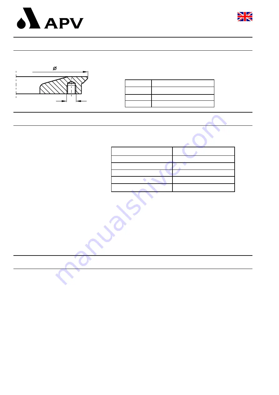
Auxiliary Equipment
UK
The tank bottom welding flange for the DKRT2 valve
does not form part of the scope of supply.
Order reference numbers for the tank bottom welding flange:
5.
Cleaning
Cleaning recommendation for the DKR valve
in the beverage industry
-
The flushing times refer to a cleaning pressure of p = 3 - 5 bar.
-
The flushing times indicated for the individual cleaning steps are
standard values. In specific applications these times must be
adjusted depending on the product, the pressure ratio and the
degree of soiling.
-
The flushing quantity per CIP spraying cycle amounts to
about 1 litre at a cleaning pressure of 3 - 5 bar.
6.
Installation
-
The valve must be installed in horizontal position at the tank bottom.
Fluids and operating leakages are, therefore, freely drainable to the
bottom and the leakage chamber drains off.
-
With several valves being parallely connected with one pipeline,
a passage of the operating leakage to the cleaning connection of
adjacent valves must be avoided.
Installation of a shut-off device or a check valve in front of the
cleaning connection is required.
-
Cleaning connection with hose 8 x 1.
-
Attention:
Observe welding instructions.
cleaning step
CIP - spraying
pre - flushing
2 x 10 sec.
caustic flushing 80° C
3 x 10 sec.
intermediate flushing
2 x 10 sec.
acid flushing
3 x 10 sec.
subsequent flushing
2 x 10 sec.
tank bottom welding flange
C
M10
DN
ref.-No.:
50
31B 31 - 08 - 030/47
80
31B
3
1 - 08 - 032/47
100
31B
3
1 - 08 - 034/47
Double - Seat Ball Valve DELTA DKRT 2
Tank Outlet Valve
Operating Manual : Rev. 4