


11. Service Instructions
The item numbers refer to the spare parts drawings
Inch and DIN designs: D4
RN 500.047.02 (see page 27)
Inch and DIN designs: D4 SL RN 501.047.02 (see page 30)
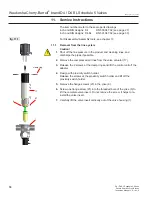
11.4. Installation of the valve insert
1.
Carefully place the valve insert in the valve housing (1) until the screw
stops.
2.
Remove the jacking screw and carefully press the valve insert into the
housing (1).
3.
Screw in the hex. screws (26) and fasten them crosswise.
4.
Place the control unit on the adapter. Make sure that the control unit is
centered on the adapter.
5.
Place the clamp ring and fasten it with the screws.
6.
Assemble the compressed air lines.
D4 Valve:
Air connection 1:
to open valve
D4 SL Valve:
Air connection 1:
to open valve
Air connection 2:
to lift upper shaft
Air connection 3:
to lift lower shaft
7.
Check the valve position indicators:
Closed valve position feedback – sensor 1 controlled
To adjust Hall sensor 1, ensure that the valve is in the closed position,
the solenoid / manual override are not activated. Turn adjustment screw
1 into the required position. The LED "Valve Closed" lights up.
Open valve position feedback – sensor 2 controlled
To adjust Hall sensor 2, first activate the solenoid valve 1, either
manually or electrically. Then turn adjustment screw 2, to adjust the
open valve position and the corresponding feedback. When it reaches
the required position, the LED “Valve Open” lights up.
Observe the switching hysteresis of the Hall effect sensors! Therefore,
adjust the switch point of the sensors with overlap in order to permit
small variations. We recommend additional 2 x 360° turns of the
adjustment screw.
8.
Design with proximity switch holder: Set the proximity switch holder
in position and fasten it with the screws. Check to see if the “Valve
Closed” or “Valve Open” message appears. Re-position the proximity
switch if required.
3
1
2
1
valve
insert
fig. 11.4.
jacking
screw
operating cams
prox. switch
holder
D4 / D4 SL with valve position indication
valve
closed
valve
open
fig. 11.4.1.
21
WCB_D4_D4SL_sch5_US.indd
D4 / D4 SL Schedule 5 Series
Double Seat Mix Proof Valves
Instruction Manual: US - rev. 0
Waukesha Cherry-Burrell
®
brand D4 / D4 SL Schedule 5 Valves


