


SPRT
9
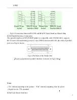
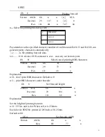
Fig.2-4Pin Order of the Serial Port
The pin assignment of serial interface is shown in Fig.2-1:
Pin No.
Signal
2 RXD
3 TXD
Source
Host
Printer
Description
Printer receives data from host
Printer transmits control code X-ON/X-OFF and
data to host
5 CTS
Printer
Signal “MARK” indicates that the printer is
“BUSY” and unable to receive data; “SPACE”
indicates that the printer
is “READY”
for receiving data.
6
DSR
Printer Signal
“
space
”
indicates that the printer is” online”
“
7 GND
8 DCD
Printer
Signal Ground
The same as CTS
Note:
Fig.2-1Pin Assignment of Serial Interface
①
“Source” denotes the source that signal comes from;
②
Logical signal level is EIA .
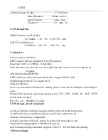
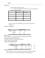
The baud rate and data structure in serial interface mode are set to 9600bps,8 data
bits ,no parity bit and1or over1stopbit(s).
The serial interface of POS5
8
Ⅳ
can be connected to standard RS-232C interface.
When connected to IBM PC or compatible machine, connection can according to
Fig2-5.


