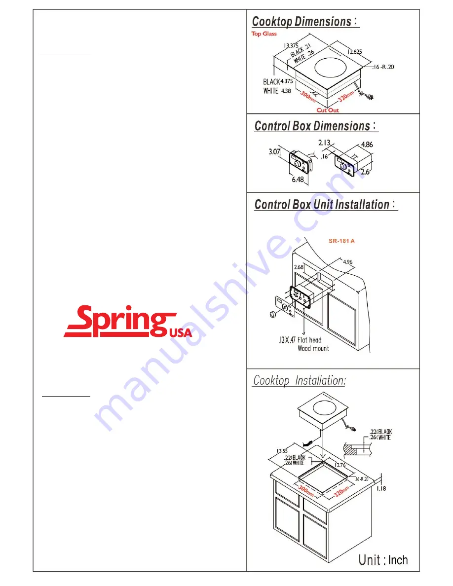
INSTALLATION:
1. Cut hole to specifications illustrated.
2. Install the control box unit before the cooktop hole on the
counter. Apply silicon to all sides of the cooktop hole on the
counter surface.
3. Gently place the cooktop into the hole and adjust its position
such that all sides are evenly flat.
4. Use the provided screws to mount the control box to the
counterside.
5. The control box has a 1.5 ft. cord; extension cords of 4.5 feet
may be purchased separately. The control box must not be
located further than 6 feet from the unit.
Attention:
1. If the ceramic glass top plate edge or surface is cracked or
broken- do not install the cooktop.
2. Silicone must be used to seal the cooktop onto the counter to
prevent spilt liquids from leaking through.
3. Counter thickness cannot exceed 1 inch.
4. Space at the rear of the cooktop must be at least 7 3/4 inches.
Note:
In the event that the rear clearance of 7 3/4" cannot be
accommodated, the unit can be turned. Clearance of 7 3/4" must
be available at the side to which the rear of the unit is turned.
5. Space at both sides of cooktop must be at least 4 inches.
6. Space beneath cooktop must be at least 7 inches.
7. SR-181A- This product’s electrical specifications
are
......
120v/60hz/1800w
and each unit must independently use a
15 amp outlet.
Absolutely do not use other appliances
on the same 15 amp circuit.
INDUCTION COOKTOP INSTALLATION


