


6
4.
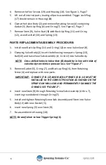
Remove the five Screws (19) and Housing (18). See Figure 1, Page 7
5.
Lift out all internal parts, leaving all parts assembled. Trigger Lock Plug
(17) should remain in Housing (18)
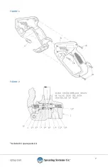
6.
Clamp the Valve Body (2) and remove Retaining Screw (4) containing
Gasket (5), Back-Up Ring (6) and O-ring (7). See Figure 2, Page 7
7.
Remove Stem (9), Valve Seat (8) with Back-Up Ring (11) and O-ring
(12), as well as Ball (10) and Spring (13).
PARTS REPLACEMENT/ASSEMBLY PROCEDURE:
1.
Install new Back-Up Ring (11) and O-ring (12) on new Valve Seat (8).
2.
Clamping Valve Body (2) insert the following new parts: Spring (13),
Ball (10) and Valve Seat Sub-Assembly (8, 11 & 12) into Valve Body.
NOTE: Cross-drilled holes in Valve Seat (8) should be in line with inlet of
valve body to minimize pressure loss. See “Figure 2”.
3.
Remove Gasket (5), O-ring (7), and Back-up Ring (6), from Retaining
Screw (4) and replace with new parts.
IMPORTANT: O-RINGS (7 & 12) AND BACK-UP RINGS (6 & 11) MUST BE
INSTALLED IN THE CORRECT POSITION AS SHOWN OR THE
SPRAY GUN WILL LEAK AND PERMANENTLY DAMAGE THE
O-RINGS. SEE “FIGURE 2”.
4.
Insert new Stem (9) through Retaining Screw Sub-Assembly (4 thru 7),
inserting rounded end through O-ring (7).
5.
Install and tighten Retaining Screw Sub-Assembly and Stem into Valve
Body (2) with new Gasket (5).
6.
Insert new Spring (3) over Stem (9).
7.
Re-assemble into Housing (18).
NOTE: Be careful not to lose Trigger Spring (3).


