5
SECTION 3
SYSTEM OVERVIEW
3.1 PRODUCT FEATURES
The Spraying Systems Co.
®
AccuCoat
®
MV10 Heated Spray System is a system that can be used in a variety of viscous
heated applications when temperature and pressure control is needed. System consists of a control panel mounted to
an optional frame and the option of Spraying Systems Co. spray control panels for spray control and operation. Power
is distributed to the pump and heater from the system control panel.
The operator controls mounted on the control panel consist of the power buttons, and various illuminated selector
switches. A lockout/disconnect switch is mounted on the door. An illuminated
“
Power On
”
pushbutton and a
“
Power
Off
”
pushbutton are located on the door. A low level indicator is illuminated when the tank is low. Illuminated selector
switches for
“
Pump On
”, “
Heater On
”,
and
“
Auto
-
Refill On
”
(optional) are used to activate said features; lamps will be
lit when features are running. The heater can be turned on only when the circulation pump is running.
Functions:
A circulating conditioning line
provides heated fluid to all the jacketed components of the system. This line consists of
a centrifugal pump, immersion heater, thermometer, pressure gauge, and return reservoir.
The centrifugal pump
circulates the heated fluid throughout all the jacketed components.
A regulator
allows for the system to be filled with a pressurized source of water or glycol solution. DI water is recom-
mended to limit mineral deposits. The regulator limits the pressure of the system for safe operation.
An immersion heater
maintains the temperature set point of the heated fluid and, by extension, the process fluid. A
pressure gauge high limit switch turns the heater off at 650°F for fail safe protection. A 50/50 mixture of propylene (or
ethylene) glycol and water must be used for temperatures of 180°F
-
200°F.
A temperature controller thermometer
provides temperature regulation to the in
-
line immersion heater. Tempera-
ture feedback is provided by the thermometer in the tank for reference.
A level switch
verifies that enough fluid is in the system so that components are not damaged. Finally a return reser-
voir provides room for expansion of the heated fluid, and pressure relief for over filling of the system.
Note:
All the conditioning lines from the pump, through all jacketed components, and back to the return reservoir
must be run in series. Never split the flow path as this could result in cold spots.
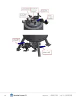
Fluid delivery is accomplished via jacketed pressure tanks, valves, hoses, and spray nozzle(s). The tank is a pressure
vessel that is pressurized with air to maintain a given setpoint at the nozzle location. To ensure constant heating the
liquid delivery components are jacketed including the ball valves mounted on the tanks. A hose delivering the fluid
from the tank to the nozzles is completely jacketed. Finally the nozzles themselves are jacketed to maintain set tem-
peratures. The tank is an ASME pressure vessel. The tank comes equipped with 125psi safety valve, air regulator, and
ball valves. The main air supply goes into the inlet 2
-
way shut off valve. The air inlet pressurizes the tank to maintain
pressure setpoint at the nozzles. Before opening the pressure tank, make sure the pressure in the system is relieved.


