Spraying Systems Co AA190DAG Series Owner'S Manual Download Page 15


AA

19

0D

AG


Ser

ies


Air


Motor

Driven


Tank


Washer


|


0

8/

1

5/

20

11


|


RE

V

.


1


15 

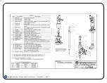
7.  Inspect O-Rings inside the upper shaft seal body 

sub-assembly (4) and seals inside pinion gear 
bushing retainer sub-assembly (22). 

8.  If damaged or worn, replace with new sub-

assemblies. 

9.  Remove any foreign material from gear teeth of the 

pinion gear bushing retainer sub-assembly (22) 
before reassembly. 

REASSEMBLY OF THE UNIT (SEE PARTS LIST PL 190DAG & PL 190DAGH) 

1.  Install one new bushing (23) into the lower end of 

the rotary Y-housing (14) and one new bushing (13) 
onto the stem (12) up to shoulder. 

2.  Slide the rotary Y-housing (14) and bushing (23) 

back onto the stem (12). 

3.  Reassemble the pinion gear bushing retainer sub-

assembly (22) onto shaft (10) by slowly rotating it as 
you slide it onto the shaft.  

This procedure will help 

prevent damage to the shaft seals inside.  

Also, be 

sure the nozzle hub gear assembly (14) and pinion 
gear bushing retainer sub-assembly (22) mesh 
properly. 

4.  Torque pinion gear bushing retainer sub-assembly 

(22) to 40 lb-ft (54 Nm). 

5.  Replace the drive plate (21) and lower screw shield 

(20). 

6.  The bottom of the shaft should pass through the 

drive link so it is about flush with the bottom of the 
drive link. 

7.  Apply Loctite 243 or 242 to threads of hex head cap 

screw (19) and thread into shaft (10). 

8.  Holding the rotary Y-housing (14), torque hex head 

cap screw (19) to 5 lb-ft (7 Nm). 

9.  Install gasket (5) onto shaft (10) at the upper end of 

the shaft. 

10. Apply Loctite 243 or 242 to threads of the upper 

shaft seal body sub-assembly (4) and reassemble 
onto shaft (10) by slowly rotating it as you slide it 
onto the shaft. 

11. This procedure will help prevent damage to the 

shaft seals inside. 

12. Torque upper shaft seal body sub-assembly (4) to 

50 lb-ft (68 Nm). 

13. Complete the reassembly by installing the groove 

pin (9) into shaft (10). 


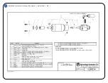
REPLACEMENT OF #46340 AIR MOTOR DRIVE (SEE PARTS LIST DRAWING PL 46340-190) 

1.  If it is not already attached, align the keyway on the 

coupling (5) with the key (6) on the gear motor sub-
assembly (11) shaft and lightly tap the coupling (5) 
until it bottoms on the shaft. 

2.  Insert the coupling (5) through the hole in the top of 

the 190 inlet casting. 

3.  The slot on the coupling (5) should be aligned and 

indexed over the groove pin and drive shaft on the 
190 assembly. 

4.  The air motor drive assembly can now be rotated 

until the through holes on inlet body align with the 
M5 female threaded inlet holes on the air motor 
drive assembly. 

5. 

Using a 4 mm hex Allen wrench, secure the gear 
motor sub-assembly (11) to the inlet body using two 
M5 bolts (1) and spring lock washers(2). 


6. 

BEFORE RE-INSTALLING IN A TANK, 
CONNECT AN AIR LINE TO THE AIR MOTOR 
DRIVE TO MAKE SURE THE UNIT WORKS 
PROPERLY.


Summary of Contents for AA190DAG Series

Page 1: ...OWNER S MANUAL MI AA190DAG DAGH AA190DAG DAGH SERIES AIR MOTOR DRIVEN TANK CLEANER Spraying Systems Co Experts in Spray Technology ...

Page 2: ...TIONS 10 11 MOUNTING 11 LIQUID INLET CONNECTION 11 MECHANICAL CLEARANCES 11 12 GROUNDING 12 HIGH IMPACT SPRAYS 12 AIR MOTOR LUBRICATION 13 AUTOMATIC LURICATION 13 OPERATION 13 MAINTENANCE REMOVAL REPLACEMENT OF SPRAY NOZZLES 14 REMOVAL REPLACEMENT OF NOZZLE HUB BUSHINGS 14 REMOVAL OF AIR MOTOR DRIVE 14 REMOVAL REPLACEMENT OF AIR MOTOR DRIVE COUPLING 14 REMOVAL OF UPPER SHAFT SEAL AND LOWER BUSHING...

Page 3: ... WITH QUALITY AND HIGH RELIABILITY WHICH HAVE BECOME SYNONYMOUS WITH THE NAME SPRAYING SYSTEMS CO THE DESCRIPTION AND SPECIFICATIONS CONTAINED HEREIN WERE EFFECTIVE ON THE REVISION DATE OF THIS MI SPRAYING SYSTEMS CO RESERVES THE RIGHT TO ALTER OR MODIFY ANY UNIT SPECIFICATION ON SPRAYING SYSTEMS CO PRODUCT WITHOUT NOTICE OR OBLIGATION INTRODUCTION THIS TANK CLEANER MEETS THE REQUIREMENTS SET FORT...

Page 4: ...NOZZLES FIT THROUGH A 4 127 MM DIA OPENING TANKS OVER THE SPECIFIED DIAMETERS COULD POSSIBLY BE CLEANED ADEQUATELY DEPENDING ON THE MAXIMUM TANK DIMENSION CLEANING SOLUTIONS BEING USED TEMPERATURES SPRAY PRESSURES FLOW RATES AND THE MATERIAL BEING CLEANED FROM THE TANK THE TANK CLEANER MAY BE USED WITH PLAIN WATER OR WITH A VARIETY OF CHEMICALS COMPATIBLE WITH 316 SS ETHYLENE PROPYLENE RUBBER AND ...

Page 5: ...RET WITH SOLID STREAM WASHJET NOZZLES 2 REO D HARDENED STAINLESS STEEL 1 4 NPT F OR 1 4 BSPT F SCE INDUSTRIAL CATALOG AND DATA SHEET 15659 I 4 1 20 mm FEATURES CAN BE PERM NENTLY INST LLED OR USCO AS A PORT ABL UNIT e DIRECTIONAL HOZZLE TURRET WITH 2 SOLID STREAM NOZZLES IS GrAR DRIVEN TO GIVE 180 O CREE COVERAGE or THE TANK BELOW THE SPRAY HEAD HITIR DRIVING UNIT IS MOUNTED OUTSIDE or TH TJ NK e ...

Page 6: ...ET PRESSURE PSI LIQUID INLET PRESSURE bar 100 200 300 400 500 7 15 20 30 35 1 4MEG 0010 3 1 4 4 5 4 6 3 7 0 11 8 17 3 20 24 26 1 4MEG 0015 4 7 6 6 8 1 9 4 10 5 17 9 26 30 37 40 1 4MEG 0020 6 2 8 8 10 8 12 4 13 9 24 35 40 49 53 1 4MEG 0025 7 7 10 9 13 3 15 4 17 2 29 43 50 61 66 1 4MEG 0030 9 1 12 9 15 8 18 2 20 4 35 51 59 72 78 1 4MEG 0035 10 5 14 8 18 1 20 9 40 59 68 83 1 4MEG 0040 11 8 16 7 20 4 ...

Page 7: ...STEEL 1 4w NPT f OR 1 4 BSPT f SEE INDUSTRIAL CATALOG AND DAT A SHEET 15659 f J 4 3 4 120 mm FEIi TURES CAN E PER AN NTLY NSTA J I QoR VSED AS A PQRTA LE 1 JNIT e D IRECTIONAL NOZZLE TURRET WITH 2 SCUD STRE t I NOZZLES IS GEAR DRIVEN TO GIVE 180 DE GREE COVERAGE OF THE T 1 NK BELOW THE SF RAY HEAD e ENTIR E ORIVING l JNIT IS t lOUNTED OUTSIDE Of THE T NK e WR Tit NI DIAMETERS UP TO AF PROXIMATELY ...

Page 8: ...4 13 9 15 2 16 4 17 5 18 6 19 6 1 4MEG 0025 7 7 10 9 13 3 15 4 17 2 18 8 20 3 1 u u r nn n Q 1 1 Q 15 8 18 2 n A 1 4MEG 0035 10 5 14 8 18 1 20 9 1 4MEG 0040 11 8 16 7 20 4 1 4MEG 0050 14 2 20 1 1I 4MEG 0060 16 4 1 4MEG 0070 18 3 1 4MEG 0080 19 9 METRIC UNITS TOTAL rLOW or 2 NOZZLES EQUAL CAPACITY LITERS PER MINUTE NOZZLE INLET PRESSURE bar SIZE 7 15 20 30 35 40 50 55 60 70 1 4MEG 0010 11 8 17 3 20...

Page 9: ...f lr VE INGINIE 0Il FOR Ll IBRICATION SE E 0 21030 1O 25 4 mm APPROX PAlirr 5 LISI f I L 46340 APPROX WEIGHT fi 25 lbs 2 8 kg A P PRO X T l ME F OR 1 0HE COMPLETE RE l OLUJIO S C l iCU I M INl ITE_S RtOUIREll f O R 1 1 1 90A G 19 lAGH CO IAF lETE PSI t5 t ii 500 I l UB l ar 1 000 I l iU1 I C iCU 8 8 10 5 16 3 6 4 7 D IU 5 5 3 5 7 35 u 4 i 9 l 9 l 9 f 1 TIU SE VALUE S A TYP ICAL CYCLE T IIM WiU VAR...

Page 10: ... WHAT THEY SIGNIFY DANGER YOU MAY BE KILLED OR SERIOUSLY INJURED IF YOU DON T FOLLOW THESE INSTRUCTIONS WARNING YOU MAY BE SERIOUSLY INJURED IF YOU DON T FOLLOW THESE INSTRUCTIONS ALL SAFETY MESSAGES WILL IDENTIFY THE HAZARD TELL YOU HOW TO REDUCE THE CHANCE OF INJURY AND TELL YOU WHAT CAN HAPPEN IF THE SAFETY INSTRUCTIONS ARE NOT FOLLOWED INSTALLATION QUALIFIED PERSONNEL MUST PERFORM ALL WORK REQ...

Page 11: ...TING BOLT OR CLAMP THE UNIT TO THE TANK TO BE CLEANED AS DICTATED BY THE MOUNTING FLANGE PROVIDED ADJUSTABLE FLANGES ALLOW EASY POSITIONING OF THE TANK CLEANING UNIT TO VARIOUS SPRAY DEPTHS FOR MAXIMUM CLEANING EFFECTIVENESS LIQUID INLET CONNECTION PROPER INSTALLATION REQUIRES LIQUID SUPPLY LINE PIPE HOSE ETC MEET OR EXCEED MAXIMUM WORKING PRESSURE USE OF PTFE PIPE TAPE OR OTHER APPROPRIATE SEALAN...

Page 12: ...ON FROM BOTH THE TANK CLEANING UNIT AND THE TANK ITSELF SHOULD BE MADE FAILURE TO FOLLOW THIS INSTRUCTION CAN RESULT IN BUILDUP OF STATIC CHARGE BETWEEN THE TANK AND THE TANK CLEANER PARTS WHICH COULD CAUSE A SUDDEN DISCHARGE OF CURRENT WITH A RESULTANT EXPLOSION OR FIRE YOU MAY BE KILLED OR SERIOUSLY INJURED IF YOU DO NOT FOLLOW THESE INSTRUCTIONS HIGH IMPACT SPRAYS THIS TANK CLEANER MAY BE EQUIP...

Page 13: ...NTAIN PROPER OPERATIONS DO NOT RUN THE UNIT DRY ALWAYS KEEP LIQUID FLOW ON BEFORE STOPPING THE AIR MOTOR WARNING DO NOT USE COMBUSTIBLE GASES TO DRIVE THE AIR MOTOR SOUND LEVEL FROM MOTOR MAY EXCEED 85DB A CHECK COMPATIBILITY OF SERVICE FLUID WITH MATERIALS USED TO CONSTRUCT THIS PRODUCT USE A PRESSURE GAUGE TO MONITOR LIQUID PRESSURE SEE 190DAG 1 FOR FLOW RATE DATA ENSURE THAT THE PUMPING SYSTEM ...

Page 14: ...243 or 242 to threads of nozzle hub post 18 and screw clockwise into rotary Y housing 14 until it seats firmly 6 Torque to 20 lb ft 27 Nm REMOVAL OF 46340 AIR MOTOR DRIVE SEE PARTS LIST DRAWING PL 46340 190 1 First make sure the unit is completely disconnected from the air source 2 Using a 4 mm Allen wrench unscrew and remove both 5 mm socket head cap screws 1 and respective spring washers 2 3 You...

Page 15: ...ad cap screw 19 and thread into shaft 10 8 Holding the rotary Y housing 14 torque hex head cap screw 19 to 5 lb ft 7 Nm 9 Install gasket 5 onto shaft 10 at the upper end of the shaft 10 Apply Loctite 243 or 242 to threads of the upper shaft seal body sub assembly 4 and reassemble onto shaft 10 by slowly rotating it as you slide it onto the shaft 11 This procedure will help prevent damage to the sh...

Page 16: ... Assembly Type 316 Stainless Steel Nozzle Solid Stream WashJet Nozzle Hclrdened Stainless Steel 1 4 NPT or 1 4 0 PT Conn 2 11 eq d ee Industrial C talog D S 15659 WashJet N JZzle Hub Po5t Tvoo 316 Stainle 5 Steel Cap Screw Hex Hd 1110 32 Stainless Steel Lower Screw Shield Tvpe 316 Stainless Steel Drive Plate Type 316 Stainle s Steel Pinion Gear Bushing Retainer Assembly Type 316 Stainless Steel PT...

Page 17: ...ssembly Type 316 Stainless Steel Nozzle Solid Strec1m WashJet Nozzle Hardened Stoiinless Steel 1 4 NPT or 1 4 PT Conn 2 Re l d ee Industrial CJtalog D S 15659 WashJet Nozzle Hub Post Type 316 Stainless Steel Cap Screw Hex Hd 1110 32 Stainless Steel Lower So ew Shield Type 316 Stainless Steel Drive Plate Tvn 316 Stc1inless Steel Pinion Gear Bushing Retainer Assembly Type 316 Sta lnless Steel PTFE C...

Page 18: ...iT MS i 1 25 i 3 mm LG moY s1Im BLACK O IDE COATl G 2 REQ D t lOIOR PINIOl I sml METRIC SET SCRrt CUP POii M 4 x 0 7 x 4 mm U 1101 Sl EEl BLACK 0 1 0 COATING I I I I I I I I I I GEAR M SU FH S SCM JLY C O NSISIS or TH OLLO UIG ITEM S 9 10 11 12 t 13 JR WOTOR GJ ST 1UP Nll 10 il l lR MOTOR MUffLE GAST JJ50 CE CERTIFlrn o S TREET ELOO N 1 8 Nl T M t 1 8 NPT f lfRASS H l Pl E N IPP I 4 NP M x 1 8 NPT...

Page 19: ...CP22023 Coupler Brass 2 CP22024 I Coupler Nipple Steel 3 CP22025 Filter Regulator 4 26383 1 4 100 Gauge 5 CP799B 7 B Close Nipple Brass 6 CP22027 Lubricator No 21030 Lubricator Assembly DESCRIPTION No 21030 WBRICATOR ASSEMBLY 8s o P O Box 71100 _ _ Wheaton II 80187 71100 Rev No Perill U t No PL 21030 Rel SHEET OF ...

Page 20: ...E CONCERNING MERCHANTABILITY AND FITNESS FOR A PARTICULAR PURPOSE BECAUSE OF THE DIFFICULTY OF ASCERTAINING AND MEASURING DAMAGES HEREUNDER IT IS AGREED THAT EXCEPT FOR CLAIMS FOR BODILY INJURY SELLER S LIABILITY TO THE BUYER OR ANY THIRD PARTY FOR ANY LOSSES OR DAMAGES WHETHER DIRECT OR OTHERWISE ARISING OUT OF THE PURCHASE OF PRODUCT FROM SELLER BY BUYER SHALL NOT EXCEED THE TOTAL AMOUNT BILLED ...

Page 21: ...AA190DAG Series Air Motor Driven Tank Washer 08 15 2011 REV 1 21 MAINTENANCE RECORD DATE PROCEDURE PERFORMED ...

Page 22: ...tion date EN 982 Safety requirements for fluid power systems and their 1996 components hydraulics EN12100 1 Safety of machinery Basic concepts general principles for 2003 design Part 1 Basic terminology methodology EN12100 2 Safety of machinery Basic concepts general principles for 2003 design Part 2 Technical principles EN ISO 14121 1 Safety of machinery Risk assessment Part 1 Principles 2007 ASM...

Page 23: ...Schmale Road P O Box 7900 Wheaton IL 60187 7901 Tel 1 800 95 SPRAY Intl Tel 1 630 665 5000 Fax 1 888 95 SPRAY Intl Fax 1 630 260 0842 Visit our Website at http www spray com Spray Nozzles Spraying Systems Co Experts in Spray Technology Spray Conlroll Spray Analysis Spray fa br T tion ...

Reviews: