background image

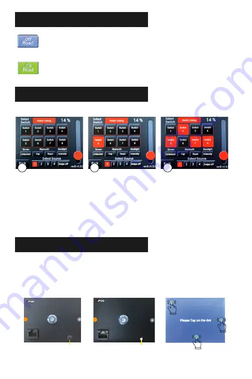
“OFF ROAD” / “ON ROAD” MODE

Selecting the “Off Road” mode enables you to use all of the flash and strobe 

features that you have programmed to use for certain switches (in the 

“Switch Feature Options” menu).

Selecting the “On Road” mode disables all the flash and strobe features. 

Switching to “On Road” will change ALL switches currently in flash or 

strobe mode to solid on.

SWITCH LINKING

In the “Switch Programming Selection Screen,” start by pressing “Link.” NOTE: Strobe 

function must be turned off before you go back into the setting to disable it. If it’s left on, 

then the strobe function will not be disabled.

Press on any switch to program it as the master switch. 

Press on all switches you wish to link the master switch. Then press “Link” and “Back.” NOTE: 

You can still use all grouped switches individually but turning on the master switch will turn 

on all switches in the group.

1

2

3

The Link option allows you to turn on multiple switches with one master switch.

PLEASE BE SURE TO ABIDE BY YOUR 

STATE LAWS WHEN USING FEATURES 

SUCH AS STROBE AND FLASH.

CALIBRATION

Use a small flathead screwdriver to pull off the small plug. This will expose the calibration 

button on the back.

While touchscreen is plugged in, press the white calibration button that is inside the access 

hole.

Follow the instructions on the screen, pressing the screen where shown. Repeat as required 

for desired results.

Replace the plug when finished.

1

2

3

4

IF TOUCHSCREEN EVER GOES INTO SLEEP MODE, PRESS THE UPPER LEFT CORNER OF THE SCREEN.

Calibration Button

Plug

2

1

3

Summary of Contents for TOUCHSCREEN

Page 1: ...R GET TO KNOW THE TOUCHSCREEN ...

Page 2: ...l panel 2 Mounting bracket assembly 3 Installation hardware 2 sheet metal screws 2 machine screws with 2 machine nuts 4 Control cable COMPONENTS INCLUDED TOOLS REQUIRED ASSEMBLY Attach bracket assembly using the 1 4 20 nut Use a 7 16 socket or open ended wrench to tighten Use a Phillips head screw driver to tighten the bracket base The bracket can be installed in two different orientations top and...

Page 3: ...s to toggle between temp modes Battery voltage meter NOTE This voltage reading is only read from the battery that the system is powered from Select to enter programming mode Select each line and enter text Max of 8 characters per line Press here to enter into the Switch Features screen When done press hold Save for 1 second changes have been saved 1 2 4 5 8 6 7 1 2 3 4 5 6 7 8 3 1 2 3 1 2 3 NOTE T...

Page 4: ...n Home screen view when locked To unlock the screen hold for 5 seconds Used to pair to the sPOD App SWITCH FEATURES This shows what switch you are currently programming PLEASE BE SURETO ABIDE BYYOUR STATE LAWS WHEN USING FEATURES SUCH AS STROBE AND FLASH 1 1 2 3 4 5 6 7 8 9 1 2 3 4 5 6 7 8 6 9 1 SLEEP MODE The Touchscreen will go into Deep Sleep after 6 hours of inactivity ie no usage of the scree...

Page 5: ...ll switches you wish to link the master switch Then press Link and Back NOTE You can still use all grouped switches individually but turning on the master switch will turn on all switches in the group 1 2 3 The Link option allows you to turn on multiple switches with one master switch PLEASE BE SURE TO ABIDE BY YOUR STATE LAWS WHEN USING FEATURES SUCH AS STROBE AND FLASH CALIBRATION Use a small fl...

Page 6: ...less software updates upgrades CAT 6 Ethernet connected up to 25 feet from BantamX Screen lock capabilities 3 75 W x 2 875 L x 625 D TOUCHSCREEN Control Panel BLUETOOTH PAIRING In Google Play for Android or iTunes for Apple search sPOD Bantam Download the sPOD app onto your smartphone or tablet Be sure that your devices Bluetooth is turned on Open the app and touch Setup 1 Touch the Scan button wa...

Reviews: