background image

(QJOLVK

8VHUPDQXDO

2

INTRODUCTION

2.1

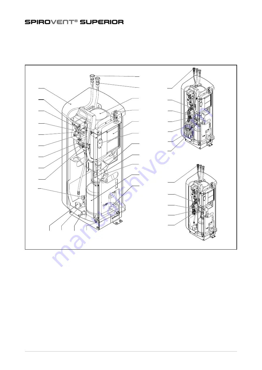
Overview of the unit

1

Outlet connection

2

Inlet connection

3

Pump

4

Power terminal

5

Control unit - Power box

6

Fuses

7

SmartSwitch

8

Automatic air vent

9

Check valve of the air vent

10

Deaeration vessel

11

Level sensor

12

Drain connection

13

Bolt

14

Valve behind the pressure gauge

15

Pressure gauge

16

Flow limiter bypass

17

Deaeration valve

18

Check valve of the outlet

19

Flow limiter outlet

20

Solenoid valve

21

Pressure sensor

22

Control unit (HMI)

23

Flow limiter inlet

24

Y-filter

25

Cover

26

Refill connection

27

Solenoid valve refill

28

Check valve refill

29

Water flow meter

30

Break tank

31

Float valve

32

Float switch

33

Flow limiter refill

S400-B

S400-R

S400

22

21

20

19

18

16

17

25

24

23

1

2

4

7

8

3

6

10

11

9

5

13

12

15

14

28

29

30

31

32

26

27

28

29

33

26

27

Summary of Contents for SPIROVENT SUPERIOR S400

Page 1: ...User Manual User Manual SPIROVENT SUPERIOR S400 EN maximising performance ...

Page 2: ...rt of this manual may be duplicated and or made public through the Internet by means of printing photocopying microfilm or in any other way without prior written permission from Spirotech bv This manual has been composed with the utmost care Should however this manual contain any inaccuracies Spirotech bv cannot be held responsible for this 1 3 Symbols Throughout the instructions the following sym...

Page 3: ...e pressure gauge 15 Pressure gauge 16 Flow limiter bypass 17 Deaeration valve 18 Check valve of the outlet 19 Flow limiter outlet 20 Solenoid valve 21 Pressure sensor 22 Control unit HMI 23 Flow limiter inlet 24 Y filter 25 Cover 26 Refill connection 27 Solenoid valve refill 28 Check valve refill 29 Water flow meter 30 Break tank 31 Float valve 32 Float switch 33 Flow limiter refill S400 B S400 R ...

Page 4: ...ons correspond with the main figure on the previous page S400 8 S400 B S400 R M PS LS PT PI FT 7 14 15 12 3 18 19 1 2 24 23 26 33 29 27 28 20 21 11 9 10 7 8 14 15 12 3 19 18 1 2 26 24 23 20 21 31 29 28 27 11 9 M PS LS PT PI FT LS 10 30 32 8 3 M PS LS PT PI 7 14 12 3 18 17 19 1 23 24 2 20 16 21 11 15 9 10 17 17 16 16 ...

Page 5: ...ill on demand of external equipment e g expansion systems The refill process consists of a vacuum phase where fresh fluid is sucked into the vessel 10 system valve 20 closed refill valve 27 opened This is followed by a flushing phase during which system fluid is flushed through the vessel to degass the refill fluid The unit can also refill the installation in case of abnormal or total pressure los...

Page 6: ... D Protection class E System pressure F System temperature G Serial number H Year of construction SPIROVENT SUPERIOR Article No Type Power input Voltage Frequency IP class Pressure PS Temperature TS Serial no Year of manufacture Spirotech bv The Netherlands A B C D E F G H ...

Page 7: ...volume m3 100 100 100 System temperature C 0 90 0 90 0 90 Ambient temperature C 0 40 0 40 0 40 Refill pressure bar n a 0 10 1 0 10 Refill temperature C n a 0 65 0 60 Effective refill flow l h n a 200 250 Item All types Supply voltage 230 V 10 50 Hz Required supply protection A 16 Nominal pump current A 3 1 Power consumption W 500 Ingress Protection class IP 44 External contacts common fault Voltag...

Page 8: ...e found in the fluid In case of a heavily contaminated system fluid a dirt separator is to be installed in the main return line of the installation Make sure that the expansion system has the proper dimensions The water displacement in the unit can cause pressure variations in the installation Take into account an extra net expansion volume of at least 2 litres Make sure the expansion system conne...

Page 9: ...t a flat closed wall Mount the unit to the floor Use brackets and adequate fasteners 2 Wall mounting Mount the unit to a flat closed wall using the holes and spacers 5 3 2 Installation Mechanical 1 Make two branch lines A on the side of the main transport line B A CAUTION Make sure that the mounting can support the filled unit empty weight 5 kg NOTE The distance between them should be at least 500...

Page 10: ...hese valves the unit can be isolated Keep valves closed until the unit is installed and taken in operation Refer to 5 4 A D B C A B C CAUTION Use a locally approved backflow protection A backflow protection can also be supplied as an option with the unit Make sure that the pressure of the feed water is below the system pressure Make sure that the lines leave the unit at the top This will avoid fas...

Page 11: ...ews B 7 Fasten the connector cap B to the connector C 8 Put back the connector in the frame 9 Fasten the cable gland A i 10 If an external contact external refill common fault and or boiler interlock or BMS is used connect the cables of the external contact or BMS to the correct connector in the power box A A A C B 9 mm A B 2 L1 N PE 1 N 1 N Contact Connector External refill Blue Common fault Grey...

Page 12: ...reak tank 5 4 2 First startup 1 Connect the unit to the mains power Automatic Commissioning Procedure The Automatic Commissioning Procedure will guide you through the startup via several screens CAUTION Make sure that the LAN cable does not touch warm parts The following processes will automatically start The unit will be filled with water Air will be released The vessel pressure will equalise wit...

Page 13: ...al date Move the wheels of the date indicator DD MM YY to the correct date in day DD month MM and year YY 5 Select the next page button Select the correct system fluid 1 Select the type of fluid in the system The indicator shows the selected type 2 Select the next page button Fill up the unit with system fluid 1 Open the valves Refer to 5 4 1 2 Select the next page button 3 Deaerate the pump Refer...

Page 14: ...play overpressure and underpressure 5 4 4 Finish the startup 1 Close the valve B behind the pressure gauge A 2 Put back the cover A on the unit and fasten it with the fastener B NOTE During the functional test warnings and faults can be triggered refer to 7 5 If this happens remedy the failure and start the functional test again If it is not possible to remedy the failure at the moment abort the f...

Page 15: ...or Description On off button Menu button Information button Home button Confirm button Next page button System connection indicator D E B C A WiFi indicator Error indicator Warning indicator Radio button not selected Radio button selected Action button available Action button not available Selection wheel Range indicator with movable labels Page Content Start On off button Home Actual unit state r...

Page 16: ...de Only accessible for Spirotech Network Shows the type of network Help Navigation buttons to go to help pages Launch guide Device description Overview External contacts Fuses Spare parts Warnings description Errors description Device info e g software version State Description Device turned OFF The unit is switched off Standby The unit is not operating and waiting for a starting command Pump test...

Page 17: ...week can be chosen Year max 5 periods per year can be chosen General settings Parameter Description Refill settings only for S400 R and S400 B versions Parameter Description Refill volume alarm after Maximum allowed refill quantity per refill Issues an alarm if a refill exceeds this threshold Range 0 2500 l 0 switched off Refill time alarm after Maximum continuous refill time Range 0 255 min 0 swi...

Page 18: ...ccur and the unit will ask whether a special refill procedure will be started to bring the system to the refill pressure again In this manual refill cycle the pump will be switched on and off and the refill valve will stay open 6 8 Various remarks When the unit is connected to mains power the display is shown automatically after touching the screen The display switches off automatically after not ...

Page 19: ...o the drain connection G 6 Drain the unit through the drain connection 7 Open the air vent screw on the main pump to completely empty the unit Refer to the figure in 5 4 1 7 4 Resetting the unit 1 At the error or warning pop up select the button CLEAR FAULT WARNING In case of a failure always warn the installer Remove the power and pressure from the unit before starting repairs Refer to 7 3 on how...

Page 20: ...o sharp bends 3 The filter 24 is clean General all types S400 S400 R S400 B Problem Possible cause Correction W1 The pressure too low A failure in the installation Make sure that the system pressure is above 1 0 bar There is a leak in the installation Repair the leak The inlet valve is closed Open the valve The pressure sensor 21 is defective Replace the pressure sensor W2 The pressure is too high...

Page 21: ...lve problem Check the valve of the air outlet 9 If necessary replace the valve E37 Pressure too high repeatedly Incompressible system Check the expansion system W38 Pressure increase too high Incompressible system Check the expansion system Only applicable to the systems with the refill functionality S400 R S400 B Problem Possible cause Correction W10 E10 Refill flow too low A valve in the refill ...

Page 22: ...ttings Refill volume alarm W24 Low level break tank The inlet valve is closed Open the valve The inlet is blocked Check and clean the inlet The float valve is broken Check or replace the float valve Only applicable to the systems with the refill functionality S400 R S400 B Problem Possible cause Correction ...

Page 23: ... free operation of the unit and system Main item Spare part Article number Pump 3 Pump 50Hz R61 418 3 Capacitor 50Hz R61 632 3 Seal set R61 631 Cover 25 Cover S400 R72 540 Control unit 5 Control unit Power Box R61 628 22 Control unit HMI R61 629 Connector for control unit Power Box R61 471 WiFi dongle USB R61 526 Fuse set Solenoid fuse 20x5 2 5AT 10 pcs Pump fuse 20x5 10AT 10 pcs Mains supply fuse...

Page 24: ...el sensor 11 Level sensor R11 559 Hoses 2 Inlet hose system to unit R61 403 1 Outlet hose unit to system R73 566 26 Refill inlet hose break tank B versions R73 562 26 Refill inlet hose mains R versions R73 566 Hose inlet to vessel R73 564 Hose inlet to vessel Refill R61 437 Hose outlet to vessel R73 565 Hose inlet to refill R73 560 Miscellaneous O ring EPDM 17 x 1 5 O ring EPDM Ø13 x 1 O ring EPDM...

Page 25: ...an Initials Nature of the maintenance Inspection date Technician Initials Nature of the maintenance Inspection date Technician Initials Nature of the maintenance Inspection date Technician Initials Nature of the maintenance Inspection date Technician Initials Nature of the maintenance Inspection date Technician Initials Nature of the maintenance ...

Page 26: ...uarantee for Spirotech products is valid until 2 years following the purchasing date The guarantee lapses in cases of faulty installation incompetent use and or non authorised personnel trying to make repairs Consequential damage is not covered by the guarantee ...

Page 27: ...Vent Superior models S4 S400 S6 S600 S10 and S16 all types Are in compliance with all relevant demands of the following European Direc ves Machine Direc ve 2006 42 EC Low Voltage Direc ve 2014 35 EC EMC Direc ve 2014 30 EU Pressure Equipment Direc ve PED 2014 68 EU Restric on of the use of certain hazardous substances in electrical and electronic equipment direc ve 2011 65 EU The following harmoni...

Page 28: ...Śƚ ƚŽ ŵĂŬĞ ĐŚĂŶŐĞƐ ǁŝƚŚŽƵƚ ƉƌŝŽƌ ŶŽƟĮĐĂƟŽŶ Copyright Spirotech bv ŶĨŽƌŵĂƟŽŶ ŐŝǀĞŶ ŝŶ ƚŚŝƐ ďƌŽĐŚƵƌĞ ŵĂLJ ŶŽƚ ďĞ ƌĞƉƌŽĚƵĐĞĚ ĐŽŵƉůĞƚĞ Žƌ ŝŶ ƉĂƌƚ ǁŝƚŚŽƵƚ ƚŚĞ ƉƌŝŽƌ ǁƌŝƩĞŶ ĐŽŶƐĞŶƚ ŽĨ ƉŝƌŽƚĞĐŚ ďǀ ƉŝƌŽƚĞĐŚ ďǀ dŚĞ EĞƚŚĞƌůĂŶĚƐ ǁǁǁ ƐƉŝƌŽƚĞĐŚ ĐŽŵ ...

Reviews: