Spirit XE 125 Owner'S Manual Download Page 9

                                                                                                                                                        XE Series Elliptical


STEP 3: CONNECTING ARM ASSEMBLY 

1.  Align the hole in the end of the Connecting Arms (L&R)(7&8)(pivoting rod end) with the 

hole in the bracket of the Lower Handle Bar (L&R) (4&5). The rod end should be on the 
inside of the Lower Handle Bar (L&R) (4&5). bracket. Take 2pcs of 5/16"×1-1/4" Hex 
Head Bolts (71) and install it through the Lower Handle Bar (L&R) (4&5)) bracket and 
the rod end. Install 2pcs of 5/16"×20×1.5T Flat Washers (98), 2pcs of    5/16"×7T 


Nylon Nuts(105) tighten firmly using the 12m/m Wrench (110) on the 5/16"×7T Nylon 
Nut (105)and one on the 5/16"×1-1/4" Hex Head Bolt (71). 

2.  Install the 2 pcs of Rails (15) into the receiving bracket in the end of Main Frame(1) with 

2 pcs of 3/8” × 2-1/4” Button Head Socket Bolts (77) , 2pcs of 3/8"×19×1.5T Flat 
Washers(94) and 2 pcs of 3/8"×7T Nylon Nuts (89) by using 2 pcs of 13/14m/m Wrench 
(111). 

3.  Put the Lug Cover (L) (61) and Lug Cover (R)(62) onto the Rail Strap (16). 

Install the Rail Tubes (15) with 2 pcs of    5/16” ×3/4” Button Head Socket Bolts (76) and 

2 pcs of    5/16"×20×1.5T Flat Washers (98) by using Combination M5 Allen Wrench & 
Phillips Head Screw Driver (108). 


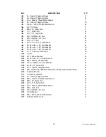
STEP 4: PLASTICS ASSEMBLY 

1.  Install the Connecting Arm Covers (L & R) (59 & 60) over the connection of the rod end 

and Lower Handle Bar (L&R) (4&5) with 4pcs of M5×15m/m Phillips Head Screws(79) 
and 2pcs of Ø 3.5×12m/m Sheet Metal Screws (84) by using the Combination M5 Allen 
Wrench & Phillips Head Screw Driver (108). 

2.  Install the 2pcs of Slide Wheel Cover (52) using the 4pcs of M5×15m/m Phillips Head 

Screws(79). 

3.  Install the Front Handle Bar Cover (L & R) (54 & 56) and Rear Handle Bar Cover (L & R) 

(55 & 57) over the Handle Bars axle connections with the 6 pcs of Ø 3.5×12m/m Sheet 
Metal Screws (84) by using Combination M5 Allen Wrench & Phillips Head Screw Driver 
(108). 


PLEASE ENSURE ALL FASTENERS ARE TIGHT AFTER THE COMPONENTS HAVE 
BEEN ASSEMBLED. 


POWER CONNECTOR LOCATED ON   
FRONT, LEFT HAND SIDE OF UNIT. 


Summary of Contents for XE 125

Page 1: ...SPT0054 PLEASE CAREFULLY READ THIS ENTIRE MANUAL BEFORE OPERATING YOUR NEW ELLIPTICAL Z100 Z300 Z500 Z700 OWNER S MANUAL...

Page 2: ...ration Instructions 4 Assembly Instructions 5 Operation of Your New Elliptical 13 Maintenance 17 Parts list 18 Explode Drawing 21 Warranty Service 22 ATTENTION THIS ELLIPTICAL IS INTENDED FOR RESIDENT...

Page 3: ...t at this time to record the name of the dealer and the date of purchase below to make any future needed contact easy We appreciate your support and we will always remember that you are the reason tha...

Page 4: ...aseous environment Never drop or insert any object into any openings Do not use outdoors To disconnect turn all controls to the off position then remove the plug from the outlet Do not attempt to use...

Page 5: ...he computer Understand that changes in resistance do not occur immediately Set your desired level on the computer console and release the adjustment key The computer will obey the command gradually NE...

Page 6: ...2 pcs 98 5 16 x 20 x 1 5T Flat Washer 4 pcs 105 5 16 x 7T Nyloc Nut 2 pcs 89 3 8 x 7T Nyloc Nut 2 pcs 94 3 8 x 19 x 1 5T Flat Washer 2 pcs Step 3 76 5 16 x 3 4 Button Head Socket Bolt 2 pcs 77 3 8 x...

Page 7: ...84 3 5x12m m Sheet Metal Screw 8pcs 79 M5 x 15m m Phillips Head Screw 8pcs Step4 Tools 108 Combination 5mm Allen Wrench Phillips Head Screw Driver 1 pc 110 12m m Wrench 1pc 111 13 14m m Wrench 2pcs A...

Page 8: ...sing the 12m m Wrench 110 NOTE There is a electrical wire running through the Console Mast Tube 10 Be careful not to damage or pinch this Computer Cable 32 during this procedure 4 Locate the Console 3...

Page 9: ...3 Put the Lug Cover L 61 and Lug Cover R 62 onto the Rail Strap 16 Install the Rail Tubes 15 with 2 pcs of 5 16 3 4 Button Head Socket Bolts 76 and 2 pcs of 5 16 20 1 5T Flat Washers 98 by using Comb...

Page 10: ...XE Series Elliptical 9 step 1 Assembly drawing...

Page 11: ...XE Series Elliptical 10 step 2...

Page 12: ...XE Series Elliptical 11 step 3...

Page 13: ...XE Series Elliptical 12 step 4...

Page 14: ...ue starting from zero The Calorie window will switch between Calories and Watts every 5 seconds The Calorie reading shows total Calories burned and is an approximate number The Watt reading indicates...

Page 15: ...reset programs to choose from After power up or reset press the Up Down keys to highlight the Program icon Press the Enter key to enter the program mode The display will show P1 for two seconds then c...

Page 16: ...ces will automatically set the target to a percent of your maximum heart rate based on your age This is why it is important to adjust the age properly The console will use a formula to determine the c...

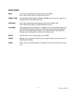
Page 17: ...set distance to zero CALORIES Accumulates calories burned from 0 to 9999 This is an estimated number only to be used from workout to workout to compare your progress Actual calorie burn cannot be meas...

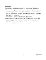
Page 18: ...wheels Clean the rails and wheels with a lint free cloth and rubbing alcohol Then apply a small amount of lubricant on the rails with your fingers or a lint free cloth You only need a thin coat of lu...

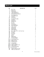
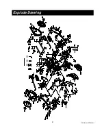
Page 19: ...eel 2 19 Rod End Sleeve 3 20 6005_Bearing 2 21 6203_Bearing 6 22 6003_Bearing 8 23 Rod End Bearing 2 24 31 25 5 19 16 3T_Bushing 4 25 Steel Cable 1 26 Drive Belt 1 27 Drive Pulley 1 28 Flywheel 1 29 M...

Page 20: ...Front Handle Bar Cover L 1 55 Rear Handle Bar Cover L 1 56 Front Handle Bar Cover R 1 57 Rear Handle Bar Cover R 1 58 32 2 5T _Round Cap 2 59 Connecting Arm Cover L 2 60 Connecting Arm Cover R 2 61 L...

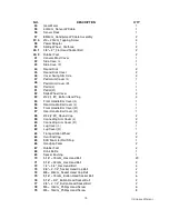
Page 21: ...asher 14 98 5 16 20 1 5T_Flat Washer 8 99 1 4 19m m_Flat Washer 13 100 J Bolt 1 101 17 _Wave Washer 6 102 5 16 23 2T_Curved Washer 2 103 M8 20m m_Carriage Bolt 1 104 17 23 5 1T_Flat Washer 2 105 5 16...

Page 22: ...XE Series Elliptical 21 Explode Drawing...

Page 23: ...ing or repairing the product at the discretion of our authorised service centre Any enquiries relating to warranties or spare parts must first be directed to Service 07 3272 7010 who will then assist...

Page 24: ...mage or misuse then there will be a call out fee of 140 depending on location Surcharge applies for non metro areas WARRANTY TERMS Warranty commences from the date of purchase from the retail store Wa...

Page 25: ...Phone Number 07 3272 7010 Email spares boylesfitness com au PLEASE NOTE that Authorised service technicians do not reside in all areas of this vast country If you live beyond the reasonable service a...

Reviews: