background image

©2017 Spireon, Inc. All rights reserved.

FL12

, 12HP/EQ

GPS Tracking Device

KIT CONTENTS:

·

 FL12/12HD Tracking Device (w/ internal antenna & 

integrated harness)

·

 Power Harness

MOUNTING HARDWARE:

• Plate Mounted Covert:

  (1x) FL12 mounting plate (3-1177)

  (2x) Serrated flange nuts

  (4x) Countersunk screws

• Nose Mount

  (2x) #10 x ¾” TEK self-drilling screws

ADDITIONAL REQUIRED HARDWARE 

(NOT INCLUDED):

• (3x) 16-22ga. ring terminals

• 6” zip-ties

IMPORTANT NOTE:

The switched power source should read 0v 

with the key in the off position and 11- 14v in 

the on position. For EQ installations, a 5-wire 

relay (not included) must be installed

CAUTION:

Us the vehicle’s factory service manual and 

a digital voltmeter to be sure that you’ve 

located the appropriate wires.

REMEMBER:

When properly installed there must be an 

unobstructed line of sight between the 

device’s antenna and the sky. Any metallic 

objects that are positioned above the device 

could interfere with GPS reception.

WIRE DESCRIPTION

DEVICE HARNESS:
Black – Power Harness (Black)
Red – Power Harness (Red)
Blue – Input 1 (- trigger)
Orange – Input 2 (- trigger)
POWER HARNESS:
Brown – J560 Pin #6
Blue – J560 Pin #7
White – J560 Pin #1

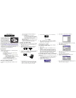
Summary of Contents for FleetLocate FL12

Page 1: ...with the key in the off position and 11 14v in the on position For EQ installations a 5 wire relay not included must be installed CAUTION Us the vehicle s factory service manual and a digital voltmet...

Page 2: ...or marker Drill the mounting holes using a 29 drill bit Carefully tap each hole with an 8 32 tap on a t handle Secure the plate to the chassis using the supplied countersunk screws Secure the FL12 to...

Page 3: ...2 to the trailer Alternatively two 10 x 1 wood screws can be used to mount the FL12 directly to the flatbed s wood floor CHASSIS MOUNT Find a mounting location under a gusset on the driver s side fram...

Page 4: ...Install cable clamps to secure the harness to the trailer PART 1 COVERT MOUNT Remove the bolts that secure the J560 housing s cover and gently pull the cover away from the housing Place the device ha...

Page 5: ...arness through the J560 housing s stock cable grommet Install zip ties and cable clamps to secure the harness to the trailer harness and trailer QUICK TIP For help with unconventioanl installations pl...

Page 6: ...s Strip the ends of the blue brown and white wires in the power harness and crimp a ring terminal onto each of them Remove the nut on the terminal for pin 1 in the j560 ground terminal and connect the...

Page 7: ...e s service manual and a digital voltmeter to locate a switched 12v power source running from the ignition switch to the ignition circuit 12v w key on 0v w key off Using the poke wrap method figure 1...

Page 8: ...lidate the installation Enter your username and password Tap sign in Search for the FL12 using the last four digits of the serial number Select the FL12 from the list to open the events list Find the...

Reviews: