


3
2.2 Sizes and pipe connections
Cooling water inlet and
BSP version
1/2" BSP
outlet connections
NPT version
1/2" NPT
Sample tube inlet and
1/2" adaptor for clamp fitting
outlet connections
(clamp not supplied) on sample inlet.
6 mm O/D on sample outlet.
Part
Design temperatures
Design pressure
572°F
(300°C)
464 psig
(32 barg)
Coil
500°F
(260°C)
638 psig
(44 barg)
248°F
(120°C)
913 psig
(63 barg)
Body
212°F
(100°C)
145 psig
(10 barg)
Cold hydraulic test pressure
232 psig
(16 barg)
Clamp
- The pressure and temperature rating is dependant on the
clamp manufacturers recommendations.
2.3 Limiting conditions
-
We recommend the use of corrosion resistant pipework suitable for
the fluid being sampled.
-
Keep the length of all pipes to a minimum.
-
Cooling water must be clean and free of scale forming salts.
-
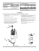
The sample cooler must be mounted vertically, using the
pre-drilled top and bottom mounting brackets (see Fig. 3).
-
Allow sufficient space below the SSC20 for collection of the
sample in a beaker or similar container. We recommend that a
tundish piped to drain is located underneath this outlet.
No connection is required on the sample OUT.
-
Connect the pipework as shown in the drawing. The cooling water
IN should be piped to the bottom of the sample cooler in 1/2"
nominal bore pipe via a cooling water inlet valve.
A 1/2" BSP/NPT male/female elbow makes a suitable connector.
-
Pipe the cooling water OUT from the top of the sample cooler to an
open drain or tundish.
Caution
: to avoid the possibility of an air lock at the top of the
sample cooler, do not allow the thread of the cooling water OUT
elbow to protrude into the sample cooler body - maximum
thread engagement 15 mm.
-
Install the clamp fitting and seal in accordance with the
manufacturer’s instructions.
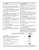
3. Installation
Note: Before actioning any installation observe the ‘Safety information’ in Section 1.
Fig. 2
Fig. 3
Sample IN
Sample OUT
Clamp
Cooling
water
IN
Cooling
water
OUT
to
drain or
tundish
.512" Dia.
(ø13 mm)
.512" Dia.
(ø13 mm)
13.79"
(350 mm)
centers
nominal


