Spirax Sarco SafeBloc DBB3 Installation And Maintenance Instructions Manual Download Page 14

IM-P184-09 

CMGT Issue 4

14

start of text under grey section header box

start of text continuing from previous page

TRANSLATION RUN OVER

6.6  How to fit the stem and bellows assembly

By following through Section 6.5 it is now possible to fit a new stem/bellows assembly (

6, 5

): 

-

Fitting this is opposite to removal - remembering to fit a bellows collar gasket (

11a

) between the bellows 

support collar and valve bonnet (

2

). 

-

Ensure the bellows collar gasket (11a) is accurately located. Before fitting the new stem/bellows assembly 

(

6 and 5

) into the bonnet (

2

). 

-

Apply a small amount of lubricating compound such as Gulf Sovereign LC grease to the end of the stem 

pin (which is pressed into the stem). 

-

Ensure the stem pin is aligned with the slot inside the bonnet. 

-

Carefully slide the stem up through the bonnet. 

-

Before screwing the end of the stem into the bonnet bush remember to fit a new stem packing ring (

8

(see Section 6.5), the original gland washer (or gland follower) and gland nut (or gland flange) over the 

stem (

6

). Do not allow the stem thread to damage the inner surface of the gland packing ring (

8

). 

-

Carefully slide the new packing ring (

8

) down the stem into the cavity and slide the original gland washer 

(or gland follower if fitted) on top of the packing ring (

8

). 

-

After the valve has been fully assembled remember to create a safe seal between the gland packing 

ring (

8

) and the stem (

6

) by tightening down the gland nut to the recommended tightening torque (see 

Table 1).

6.7 How to fit the disc

By following through Section 6.5 it is now possible to replace the valve’s disc: 

-

To replace the disc (

4

) simply remove the old stem pin and replace the disc (

4

). 

-

Attach the new disc with the new stem pin (supplied). Where the disc (

4

) is attached using a retaining 

nut and collet arrangement, simply prise the crimped skirt away from the retaining nut and unscrew. 

Remove the collets remembering to save these and the retaining nut as they are not supplied as spares. 

Fitting is the opposite to removal but ensure the collets and threads are lightly greased with lubricating 

compound such as Molybdenum Sulphide.

-

If a new disc is being fitted then crimp the collet retaining nut securely across two corners by deforming 

the disc’s thin metal skirt. If the original disc is being fitted then re-crimp using a fresh part of the skirt.

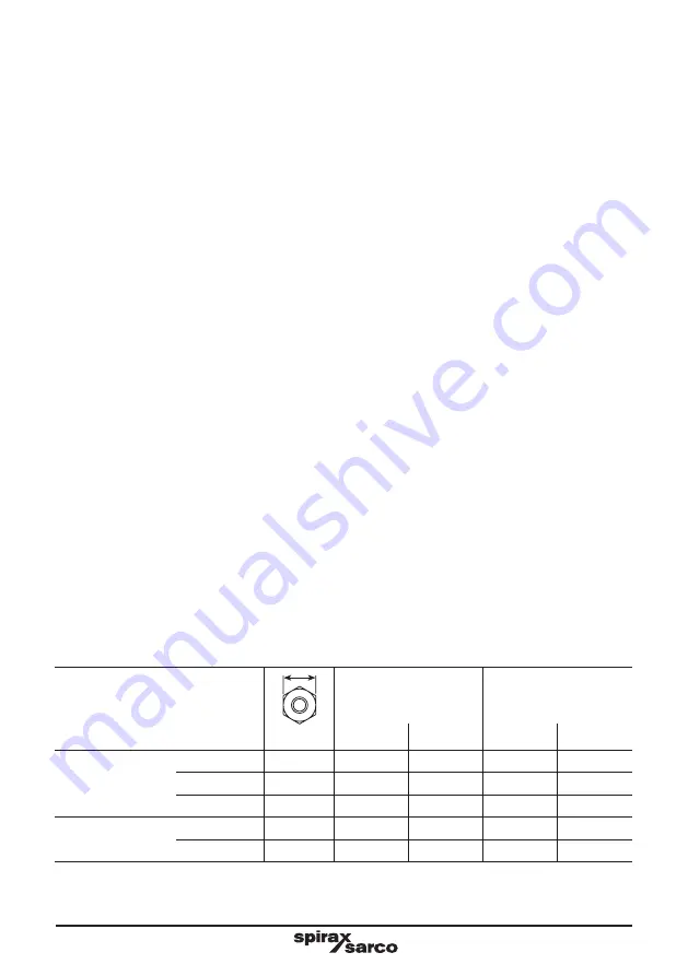
Table 1  Recommended tightening torques

Item

Size

PN40

ANSI 300

mm

N m

(lbf ft)

N m

(lbf ft)

Bonnet bolts and 

nuts (9 & 10)

DN15 - DN25

17 A/F

35 - 40

(26 - 29)

50 - 55

(36 - 40)

DN40 - DN65

19 A/F

55 - 60

(40 - 44)

85 - 90

(63 - 66)

DN80 - DN100

24 A/F

130 - 140

  (95 - 103)

190 - 200

(140  - 147)

Gland nut

DN15 - DN80

22 A/F

5 - 10

(  3.5 - 7)

5 - 10

(  3.5 - 7)

DN100

32 A/F

15 - 20

(10.5 - 14  )

15 - 20

(10.5 - 14)

Summary of Contents for SafeBloc DBB3

Page 1: ...ct information 3 Installation 4 Commissioning 5 Operation 6 Maintenance 7 Spare parts Copyright 2018 Printed in GB 1849050 3 Spirax SafeBlocTM DBB3 Double Block and Bleed Bellows Sealed Stop Valve Ins...

Page 2: ...are in Group 2 of the above mentioned Pressure Equipment Directive ii Check material suitability pressure and temperature and their maximum and minimum values If the maximum operating limits of the p...

Page 3: ...hocks 1 7 Pressure systems Ensure that any pressure is isolated and safely vented to atmospheric pressure Consider double isolation double block and bleed and the locking or labelling of closed valves...

Page 4: ...C 752 F Many products are not self draining Take due care when dismantling or removing the product from an installation refer to Maintenance instructions 1 14 Freezing Provision must be made to protec...

Page 5: ...P or socket weld connection and must be stated at the time of order placement Standards This product fully complies with the requirements of the Pressure Equipment Directive PED and carries the mark w...

Page 6: ...nimum operating temperature Note For lower operating temperatures consult Spirax Sarco 10 C 14 F Designed for a maximum cold hydraulic test pressure of 60 bar g 870 psi g Body design conditions ANSI 3...

Page 7: ...efore commissioning of the line 3 3 The valve can be installed in the horizontal or vertical plane When installed in the horizontal plane the bleed port should ideally be positioned at the bottom see...

Page 8: ...ly closed 5 3 If valve keys are used care must be taken not to use excessive force when opening or closing the valve 5 4 A Valve Integrity Test must be undertaken prior to each double isolation of the...

Page 9: ...harge after a short period consult Spirax Sarco Service Department Note Handwheels should always be opened slowly to avoid system shocks Operation sequence for the Spirax SafeBlocTM Flow Left to Right...

Page 10: ...reassembling ensure that all joint faces are clean Ensure that the correct tools and necessary protective equipment are used at all times When maintenance is complete open isolation valves slowly and...

Page 11: ...sh isolation integrity Step 4 Depressurise the downstream system Step 5 It is now safe to maintain the downstream system Return to Step 1 Please note The Spirax SafeBlocTM is shown with the bellows se...

Page 12: ...be unscrewed from the bonnet bush When the stem 6 is disconnected from the bonnet bush unscrew the gland nut and remove both this and the gland washer Keep these parts safe as they are not supplied a...

Page 13: ...IM P184 09 CMGT Issue 4 13 Fig 4 7 Bonnet bush 10 Bellows support collar 1 9 11b 5 11a Position indicator clip on 6 8 Gland washer Gland nut Locking screw Main handwheel nut 2...

Page 14: ...fully assembled remember to create a safe seal between the gland packing ring 8 and the stem 6 by tightening down the gland nut to the recommended tightening torque see Table 1 6 7 How to fit the disc...

Page 15: ...6 8 Gland washer Gland nut Locking screw Main handwheel nut 2 6 8 Final assembly Ensure the bellows support collar and gaskets 11a and 11b are accurately aligned with the bonnet 2 before final assemb...

Page 16: ...overhaul of the valve 2 x each spare is required 7 Spare parts How to order spares Please note for customer convenience spares are supplied in kits to ensure all the appropriate replacement parts are...

Reviews: