Spirax Sarco MFP14-PPU Installation And Maintenance Instructions Manual Download Page 6

IM-P681-02 

 ST Issue 2

6

2. General product information

2.1 Description

The Spirax Sarco MFP14-PPU vented automatic pump packaged units are plug-in systems 

specifically designed to collect and pump hot condensate; commonly returned for use as 

boiler feedwater.

The MFP14-PPU is available with either single, duplex or triplex pumps, mounted on a single 

base plate, that can be used for duty only or duty / stand-by applications.

Operated by steam, the MFP14-PPU can be tailored to suit a wide range of condensate 

handling applications.

The standard pump is manufactured from SG iron, although cast steel and stainless steel 

versions are available on request.

Please note: 

Versions suitable for use with compressed air as the motive power and or other 

combinations are available as bespoke items. For further details contact your local Spirax 

Sarco office or representative.

Optional extras

A pump insulation jacket is available at extra cost - see TI-P136-07.

Standards 

The MFP14-PPU fully complies with the requirements of the European Pressure Equipment 

Directive 97 / 23 / EC and carries the       mark when so required. 

All welding is in accordance with the requirements of the European Pressure Equipment 

Directive  97 / 23 / EC  (PED).

Certification

This product is available with a declaration of conformity. For other certification requirements 

contact Spirax Sarco.  

Note: 

All  certification  /  inspection  requirements  must  be  stated  at          

the time of order placement. Retrospective certification / inspection may not be possible.

Note:


For additional product data see Technical Information sheet TI-P680-03.
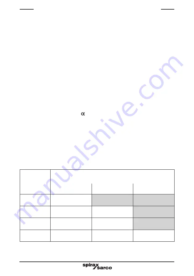
2.2 Capacities

Unit size

Approximate maximum capacities kg / h (with 4M lift). 

See separate TI sheet for full capacity details. 

Single

MFP14-PPU

Duplex

MFP14-PPU

Triplex

MFP14-PPU

DN25

(1")

1 300

DN40

(1½")

2 000

4 000

DN50

(2")

4 000

8 000

DN80 x DN50

(3" x 2")

6 000

12 000

18 000

Summary of Contents for MFP14-PPU

Page 1: ...sioning 4 Duplex MFP14 PPU installation and commissioning 5 Triplex MFP14 PPU installation and commissioning 6 Maintenance 7 Fault finding Copyright 2012 Printed in the UK Triplex MFP14 PPU shown MFP1...

Page 2: ...IM P681 02 ST Issue 2 2...

Page 3: ...n other fluids may be possible but if this is contemplated Spirax Sarco should be contacted to confirm the suitability of the product for the application being considered ii Check material suitability...

Page 4: ...ble block and bleed and the locking or labelling of closed valves Do not assume that the system has depressurised even when the pressure gauge indicates zero 1 8 Temperature Allow time for temperature...

Page 5: ...4 Freezing Provision must be made to protect products which are not self draining against frost damage in environments where they may be exposed to temperatures below freezing point 1 15 Disposal Unle...

Page 6: ...your local Spirax Sarco office or representative Optional extras A pump insulation jacket is available at extra cost see TI P136 07 Standards The MFP14 PPU fully complies with the requirements of the...

Page 7: ...93 C MFP14 300 C 12 8 bar g TMA Maximum allowable temperature MFP14S 300 C 10 8 bar g MFP14SS 300 C 9 3 bar g Minimum allowable temperature 0 C MFP14 13 8 bar g 198 C PMO Maximum operating pressure MF...

Page 8: ...ASME 150 2 ASME 150 6 ASME 150 2 ASME 150 Duplex MFP14 PPU For further information regarding installation location and commissioning see Section 4 Unit size Pipe connection V Con out W Motive X Overfl...

Page 9: ...IM P681 02 ST Issue 2 9 Fig 1 Single MFP14 PPU Fig 2 Duplex MFP14 PPU Fig 3 Triplex MFP14 PPU Y Z Z X W V Y Z Z X W Z Z Y X V W V V V...

Page 10: ...n A maximum flash velocity in the receiver of 20 m s A maximum vent velocity of of 30 m s A maximum unrestricted vent pipe length of 10 m A maximum condensate inlet pressure discharge from steam traps...

Page 11: ...d now start to flow into the main receiver item 1 and into the pump item 3 when the plant is operational 5 Check all flanged screwed connections for any leakage 6 Observe operation for any abnormaliti...

Page 12: ...0S2 RB ball valve straight handle Carbon steel 8 PC10 Quick fit connector Stainless steel 9 UTD30L thermodynamic steam trap Stainless steel 10 Steam inlet drain trap flexible hose Mild steel stainless...

Page 13: ...50 2 200 mm 8 DN80 x DN50 3 x 2 200 mm 8 The recommended receiver vent size is based on A maximum flash velocity in the receiver of 20 m s A maximum vent velocity of of 30 m s A maximum unrestricted v...

Page 14: ...turn line point V 4 Condensate should now start to flow into the main receiver item 1 and into the pump item 3 when the plant is operational 5 Check all flanged screwed connections for any leakage 6 O...

Page 15: ...on steel 8 PC10 Quick fit connector Stainless steel 9 UTD30L thermodynamic steam trap Stainless steel 10 Steam inlet drain trap flexible hose Mild steel stainless steel 11 Exhaust flexible hose Mild s...

Page 16: ...ess equipment being drained 4 Connect a U bend water seal to the overflow point X and ensure that it is connected to a safe discharge point Ensure a suitable amount of water is filled into the U bend...

Page 17: ...n steel 8 PC10 quick fit connector Stainless steel 9 UTD30L thermodynamic steam trap Stainless steel 10 Steam Inlet flexible hose Mild steel stainless steel 11 Exhaust flexible hose Mild steel stainle...

Page 18: ...PPU is safely secured When dismantling the pump care should be taken to prevent personal injury from the strong snap mechanism Always handle with care For full maintenance instructions on each compone...

Page 19: ...rom pump to condensate return line Motive pressure insufficient to overcome backpressure Check motive pressure and static backpressure Ensure motive pressure is higher than the static backpressure to...

Page 20: ...IM P681 02 ST Issue 2 20...

Reviews: