


IM-P006-07
CTLS Issue 12
14
3.11 Safety valve
A safety valve should be fitted to protect the downstream equipment from excessive pressure. It should be
set to lift below the safe working pressure of the downstream equipment, and will normally be sized to pass
the full capacity of the PRV should the PRV fail in the fully open position. The safety valve set pressure
should take account of its reseat characteristic and the 'No-load' pressure setting of the PRV. For example,
the typical blowdown value (reseat differential) for a DIN type safety valve is 10% of set pressure. The
minimum possible safety valve set pressure must therefore equal the no load set pressure of the reducing
valve plus the blowdown value of the safety valve plus a small margin of at least 0.1 bar. If the set pressure
is any lower, if whatever reason the safety valve lifts it will not shut properly and will simmer, creating a leak
which is often wrongly diagnosed as a result of a leaking reducing valve.
Discharge pipework should be taken to a safe place.
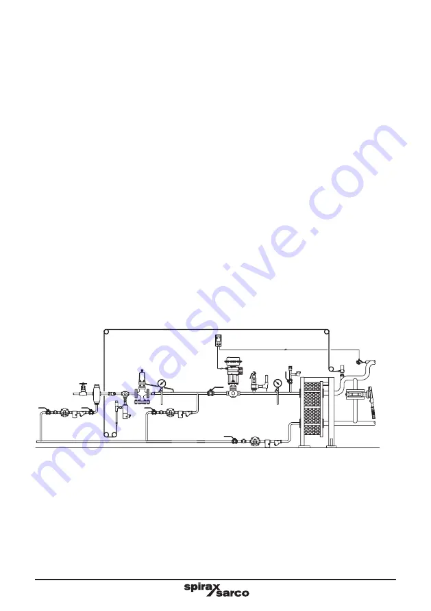
3.12 Position in relation to other control valves
Line or system isolation valves (
A
), either remotely actuated or manual, should be installed on the upstream
side of the DP reducing valve.
Where there is downstream control equipment (
B
), particularly when it is fast acting (for instance pulsed
piston actuated valves) ensure the control equipment is at least 50 pipe diameters away from the DP to
prevent pressure pulses being transmitted back causing unstable operation and premature wear or if this is
impractical an intermediate vessel can provide a similar benefit.
Where a safety valve (
C
) is required to protect the system downstream of a DP and where a control valve is
also being used downstream of the DP, it is recommended that the safety valve is fitted downstream of the
control valve rather than in between the DP and the control valve. If any slight leakage occurs this will avoid
any pressure build-up causing nuisance operation of the safety valve but provide complete protection for
the downstream system.
Where valves are installed downstream of the DP (
B
) the intermediate downstream pipework must be properly
trapped (
D
) to ensure no condensate can buil up on the downstream side of the DP.
Fig. 6 The position of the pressure reducing valve in relation to other
control equipment
D
C
B
A
A
Summary of Contents for DP143
Page 2: ...IM P006 07 CTLS Issue 12 2...
Page 28: ...IM P006 07 CTLS Issue 12 28...


