background image

Ex

pl

od

e

d V

ie

w

(V

u

e ec

la

tee

)

8

5

2

8a

7

1

6

3

4

8b

9

10

11

 -

 D

ia

g

ra

m

 4

Ho

riz

on

ta

l Mo

u

nt

 Vi

e

w

(Install

at

ion

 ho

ri

zon

ta

le

)

11

9

1

2

5

6

3

8a

8b

Ve

rtic

al

 M

o

un

t V

iew

(Install

at

ion

 v

er

tic

al

e

)

8

7

Di

a

gr

a

m 2 -

Di

a

gr

a

m 1 -


7

11

It

e

m N

o  

Pa

rt  

 Q

u

an

tit

y

1  

Mo

u

lde

Pl

a

te

 Ou

ter


 1

2  

Mo

u

lde

Pl

a

te

 In

n

e

r  

1

3  

Gr

u

b S

cr

ew 

  3

4  

Bo

ss  

  1

5  

‘O

’ r

ing


   1

6  

Se

a

li

n

W

ash

er


  1

7  

 D

e

lr

in

 S

p

ac

e

r (

Bl

a

ck

 4

8  

M5

 sc

rew

, c/

h

d

 x

 60


4


8a  

M5

 sc

rew

, c/

h

d

 x

 4

0  

4

8b  

M5

 sc

rew

, p

a

n h

ead

 x

 3

0

4

9  

M5

 Ny

loc

 Nu

t

 4

10


 S

lee

ve


   1

11

Ny

lon

 S

pac

e

r (

Wh

ite

)

4  

No

te:

Fo

v

e

rt

ica

l moun

ting 

of 

th

ro

ttl

bo

d

y u

se 

it

em

8

 a

n

d 9

.

(P

o

ur l`instal

la

tion 

v

er

tic

al

d

e l

`u

n

it

d

e c

omm

an

d

e de

s ga

z,

 u

ti

lise

le

s a

rt

icl

e

s 8

 e

9

.)

Fo

H

o

ri

zon

tal

 m

ou

n

ti

ng

 of 

th

ro

ttl

bo

d

y u

it

em

8

an

d

 8

b

(

Po

u

r l`instal

la

tion

 h

or

iz

o

nt

a

le

  d

l`un

ite

 de c

om

m

an

de de

s g

az,

 u

ti

lise

z

le

ar

tic

le

s 8a

 e

8

b

.)

Summary of Contents for ATCU/1

Page 1: ...Unit ATCU de commande des gaz ATCU 1 ATCU 1 Installation and Maintenance Instructions Instructions d installation et de maintenance English page 1 Francais page 5 Tel 44 0 1983 295555 email prosuppor...

Page 2: ...hich may not be required 3 Position the face plate and 4 fasteners Fastener choice Item 8 or 9 is dependant on your choice of horizontal or vertical mounting 4 Install the black spacers Item 7 on the...

Page 3: ...urchased separately Throttle gear levers and cable ends should not interfere with each other on the reverse of the throttle control unit Item purchased separately Note For outboard engines add 1 25m 4...

Page 4: ...nti re ment L anneau de protection article 10 est optionnel 3 Mettez en place la plaque frontale avec les 4 vis Le choix des vis article 8 ou 9 d pend de l installation horizontale ou verticale 4 Inst...

Page 5: ...nt de percer le pont V rifiez l enclenchement des engrenages et assurez vous que la manette des gaz soit sur le neutre c est dire bouton enfonc V rifiez la propulsion avant et arri re avant de d marre...

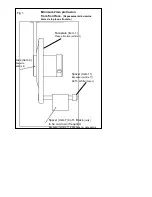
Page 6: ...s 2mm de la plaque frontale Faceplate Item 1 Plaque frontale article 1 Spacer Item 11 Espaceur article 11 4off white blanc Spacer Item 7 4 off Black noirs to be cut down if required Espaceur article 7...

Page 7: ...s 1 5 O ring 1 6 Sealing Washer 1 7 Delrin Spacer Black 4 8 M5 screw c s hd x 60 4 8a M5 screw c s hd x 40 4 8b M5 screw pan head x 30 4 9 M5 Nyloc Nut 4 10 Sleeve 1 11 Nylon Spacer White 4 Note For v...

Reviews: