background image


SK597-AT4 
Hydraulic system 
Truck  


8-6 

SPIERINGS MOBILE CRANES USER MANUAL V 1.2 


M

ei

 2

0

1

8


C

h

a

n

g

e

s

 a

n

d

 t

y

p

o

g

ra

p

h

ic

a

l e

rr

o

rs

 r

e

s

e

rv

e

d

©

 2

0

1

8

 S

p

ie

ri

n

g

s

 M

o

b

ile

 Cr

a

n

e

s

 –

 A

ll r

ig

h

ts

 r

e

s

e

rv

e

d


8.3.3. 

Replacing the hydraulic fine filter at rear axle steering 

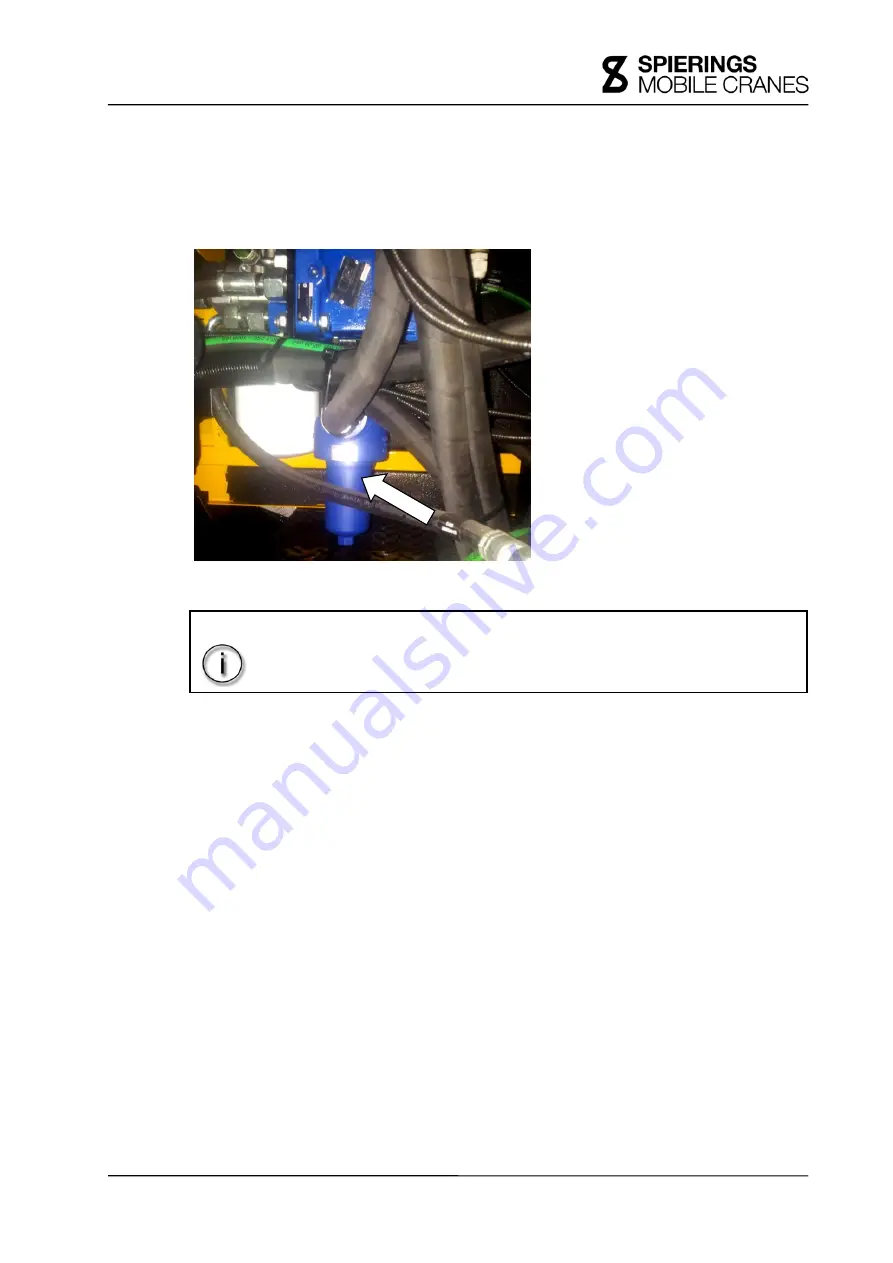
The hydraulic system of the rear axle steering is equipped with a hydraulic fine filter. 

The fine filter is situated in the left-hand engine cowling, next to the coarse filter behind the electrical 

cabinet (se

Picture 8-5

). 


For replacing the hydraulic fine filter, the following steps must be carried out: 

1.  Turn off the diesel engine of the truck; 

2.  Place an oil tray under the filter; 

3.  Unscrew the bottom of the filter (wrench width 19); 

4.  Remove the filter from the holder; 

5.  Clean the holder, if necessary, with a lint-free dry cloth; 

6.  Replace the O-ring by a new one, which is lightly greased (see 

§ 14.4. Specifications 

hydraulic system truck

); 

7.  Replace the fine filter by a new one (see 

§ 14.4. Specifications hydraulic system truck

); 

8.  Mount the bottom of the fine filter. 


If there are problems with the rear axle steering, the hydraulic fine filter should be checked. 

For more information, see 

§ 5.3.6. Maintenance schedule hydraulic system truck. 


INFORMATION! 

Replace this fine filter once per 5 years when the coarse filter is removed,  
related to limited working space. 


Picture 8-5 


Summary of Contents for SK597-AT4

Page 1: ...ical descriptions and maintenance instructions are given in the maintenance section of this manual 2018 Copyright Spierings Mobile Cranes All rights reserved No part of this publication may be reprodu...

Page 2: ...rator driver must strictly comply with the instructions in the manual and possible additions thereto The user operator driver must keep strictly to the lifting specifications as indicated on the Spier...

Page 3: ...am You are receiving this email so that you can gain access to the documentation accompanying your Spierings crane These documents are available as PDF files and are released per crane number The docu...

Page 4: ...l rights reserved Explanation of the used symbols Information Toxic substances Wear safety glasses Dangerous for hands Wear safety gloves Do not come in turning radius Wear safety shoes Corrosive subs...

Page 5: ...k 2 1 2 2 Keys 2 2 2 3 Truck cab 2 3 2 3 1 Fuse box 2 4 2 3 2 Central console 2 5 2 3 3 Parking heater 2 6 2 3 4 Tachograph 2 7 2 4 Engine cowling 2 8 2 4 1 Left hand engine cowling 2 9 2 4 2 Right ha...

Page 6: ...error message s display gearbox 3 46 3 9 5 4 Error history display gearbox 3 47 3 9 6 Control panel steering system 3 47 3 9 6 1 Keys control panel steering system 3 48 3 9 6 2 Display control panel...

Page 7: ...ine speed control ESC 4 32 4 11 Uphill and downhill driving 4 33 4 12 Refuelling 4 34 4 12 1 Refuelling diesel 4 34 4 12 2 Refuelling AdBlue 4 35 4 13 Off the road driving 4 37 4 13 1 Axle load 4 37 4...

Page 8: ...linder and luffing cylinders 5 2 5 1 5 Lift 5 2 5 1 6 Outrigger system 5 2 5 2 Maintenance truck after commissioning 5 3 5 2 1 First service truck 5 3 5 3 Maintenance schedule truck 5 4 5 3 1 Maintena...

Page 9: ...ontour lights 7 11 7 11 2 Rear contour light 7 12 7 12 License plate lights 7 13 7 13 Rotaflares 7 14 7 14 Work lamps 7 15 8 Hydraulic system 8 1 8 1 Hydraulic tank 8 1 8 1 1 Checking oil level 8 2 8...

Page 10: ...truck 10 11 10 3 7 Cleaning air filter diesel engine truck 10 12 10 3 8 Replacing air filter element diesel engine truck 10 13 10 4 Fuel system diesel engine truck 10 14 10 4 1 Checking fuel system 10...

Page 11: ...5 13 Lubrication 13 1 13 1 Automatic lubrication system truck 13 1 13 1 1 Grease pump 13 1 13 1 2 Timer 13 2 13 1 3 Lubrication points central lubrication system 13 3 13 2 Manual lubrication truck 13...

Page 12: ...SK597 AT4 Table of contents Truck XII SPIERINGS MOBILE CRANES USER MANUAL V 1 2 Mei 2018 Changes and typographical errors reserved 2018 Spierings Mobile Cranes All rights reserved...

Page 13: ...ts of the SK597 with the AT4 carriage The measurements given are the overall dimensions axle bases and turning circle see also picture in the Annexes 1 1 Dimensions and weight Length 15 98 m Width 2 7...

Page 14: ...nt in opposite direction till 50 kph 31 mph 1 3 2 Off the road steering There are special steering programs which are only available in off the road mode see 4 13 5 Manoeuvering Steering system Small...

Page 15: ...left Stamped in the right hand frame girder in front of the first axle Picture 1 2 right In case there is help needed from ITS International Truck Service of DAF Trucks N V the chassis number will be...

Page 16: ...SK597 AT4 General data Truck 1 4 SPIERINGS MOBILE CRANES USER MANUAL V 1 2 Mei 2018 Changes and typographical errors reserved 2018 Spierings Mobile Cranes All rights reserved...

Page 17: ...rstructure slewing rim F Truck ladder see 2 10 Truck ladder G Buffer beam H Rear toolbox optional see 2 9 Rear toolbox optional I Filler neck fuel tank see 2 5 Outriggers J Outriggers see 2 5 Outrigge...

Page 18: ...fuel tank G Key operated selector switch Key operated selector switch full reduced outrigger base Key operated selector switch emergency control lift on off Key operated selector switch emergency con...

Page 19: ...Battery charger remote control batteries see 3 6 Battery chargers remote control batteries G Steering wheel H Control panel see 3 9 Control panel I Windscreen wipers see 3 9 Control panel 42 Control l...

Page 20: ...s side of the truck cab under the cover of the dashboard Open fuse box 1 Remove the two turning knobs at the front of the cover 2 Open the cover the cover can be fixed by means of support A Picture 2...

Page 21: ...s side consists of Picture 2 5 A Diagnostic connector OBD On Board Diagnostics for diagnosis of the full drive line consists of Diesel engine truck Gearbox Retarder Dashboard B Diagnostic connector st...

Page 22: ...ndscreen wipers B Relays indicators C Gateway D Control module anti blocking system ABS E Control module steering system F Control module gearbox G Switches transfer case neutral and ABS reset H Contr...

Page 23: ...or in the tachograph has occurred This error message usually disappears as the tachograph is reset Reset tachograph 1 Remove the upper tachograph disc from the holder if a disc is present Picture 2 8...

Page 24: ...g cross key engine cowling truck The engine compartment is divided into three sections 1 to 3 A Left hand cover B Left hand cover plate C Central cover plate D Cover plate truck cab E Right hand cover...

Page 25: ...lubrication system truck F Hydraulic blocks suspension system G Control cabinet for the benefit of the suspension and outrigger system H Emergency control unit not shown in picture it is located right...

Page 26: ...he outrigger pad holders E can be used as support to step on the outrigger beam In transport mode the outrigger plate F must be pushed over outrigger plate guide H The outriggers can be operated from...

Page 27: ...t steps for adjusting the work lamps properly Turn the knob A on the bracket counterclockwise see Picture 2 14 After adjusting fix the work lamp by turning the knob clockwise 2 7 Storage box There are...

Page 28: ...of the truck 2 10 Truck ladder To climb safely on the crane platform a ladder is mounted at both sides of the truck Picture 2 15 There is also an auxiliary ladder available in the engine cowling of t...

Page 29: ...aphical errors reserved 2018 Spierings Mobile Cranes All rights reserved 2 13 Battery cabinet Between the 2nd and the 3rd axle on the driver s side the batteries of the truck are installed see Picture...

Page 30: ...SK597 AT4 Introduction to the truck Truck 2 14 SPIERINGS MOBILE CRANES USER MANUAL V 1 2 Mei 2018 Changes and typographical errors reserved 2018 Spierings Mobile Cranes All rights reserved...

Page 31: ...pwards The door can be locked from the outside by using the door key Open turn the door key in the direction of the front of the vehicle Lock turn the door key in the direction of the rear of the vehi...

Page 32: ...with an integrated seat belt see Picture 3 1 Driver s seat A Inertia reel seat belt B Seat belt see 3 2 2 Seat belts D Back adjustment E Chair seat adjustment F Transfer lift G Tilting the seat H Heig...

Page 33: ...ired position by pushing the seat Release the lever F Transfer lift Lever downwards when seat is in driving position seat will go to its lowest position Lever upwards when seat is lowered seat will go...

Page 34: ...ions properly 3 Release the seat belt 3 2 2 3 Check seat belts Check the seat belts for wear Check its operation by jerking the belt from its winding mechanism The belt must be locked immediately Have...

Page 35: ...witch mirror heating 3 4 Sun blinds To prevent sunlight from blinding a sun blind is mounted above the windscreen for both the driver and the co driver Pull down Pull down the blind with the joggle A...

Page 36: ...he charging unit for the batteries of the remote controls is found at the left under the dashboard at the driver s side The batteries will always be charged even if the main switch truck is not enable...

Page 37: ...at the top 3 8 Fire extinguisher The fire extinguisher is situated behind the driver s seat At the right side behind the control box in the crane cab there is a second fire extinguisher present CHECK...

Page 38: ...8 Spierings Mobile Cranes All rights reserved 3 9 Control panel The control panel Picture 3 6 is located on the dashboard and to the right side of the driver CAUTION The switches and control panels in...

Page 39: ...ferential lock 3 Switch transfer case high low This switch enables the driver to switch to high or low gear Switch to road mode high hare when driving on public or paved roads Switch to off the road m...

Page 40: ...no indicator visible on the control panel 9 Switch work lamps at engine cowling Using this switch the work lamps at the rear of the engine cowling are switched on or off see 7 14 Work lamps 10 Switch...

Page 41: ...the right hand rear move in or out simultaneously see 4 13 2 Axle height adjustment 17 Switch levelling Using this switch the truck will be levelled automatically the suspension cylinders are moved t...

Page 42: ...5 2 2 Crane set up 22 Switch outrigger left hand rear in out Using this switch the outrigger on the left hand at the rear moves in or out see Crane manual 5 2 2 Crane set up 23 Switch outrigger right...

Page 43: ...to move the window at the driver s side up or down Operating the switch is only possible when the ignition is turned on 29 Switch door window co driver s side This switch enables the driver to move t...

Page 44: ...r kph mph The truck has a limited speed of 83 kph 52 mph The total number of kilometres driven and the mileage of the trip recorder are shown on the display below the speedometer The current time is a...

Page 45: ...sed to the tactile resistance the indicator lights will flash once When the lever is pushed over the tactile resistance the indicator lights will flash until the steering wheel is turned back to the c...

Page 46: ...Position 2 Screen wipers speed fast The screen wipers are only functioning when the ignition is turned on 7 Windscreen washers 3 7 Windscreen washer reservoir When the spring loaded switch Picture 3 7...

Page 47: ...uise control engine speed control is switched off spring returned LIM The variable vehicle speed limitation device is switched on move back to centre position to switch off the device 2 By pressing th...

Page 48: ...ering programs The control panel can be used to select and set the steering programs For using the control panel steering system the steering system must be switched to off the road mode Use 32 Switch...

Page 49: ...n reverse Camera image side view camera by using the right hand flashing light Up side view camera optional Down reverse drive camera 52 Digital tachograph For more information see the supplied manual...

Page 50: ...itch truck This switch is used to switch on or off the electrical system of the truck The positive terminal is hereby interrupted If the switch is turned to the longitudinal vehicle direction the elec...

Page 51: ...light the vehicle need not to be stopped take corrective actions at the first opportunity Error message light red At a serious malfunction the error message light will be active always in combination...

Page 52: ...indicator or alarm lights are enabled Status X Active during first 3 seconds when ignition truck is switched on X Active when there is a serious malfunction in one of the systems STOP IMMEDIATELY The...

Page 53: ...mbols or text lines In the top bar A of the screen current warnings are displayed in red and yellow If more than seven warnings are active these warnings can be displayed on another screen see 3 9 2 6...

Page 54: ...X X If the ignition is switched on and the engine is not running this symbol flashes system check 5 seconds on and 10 seconds off Another flashing pattern indicates an error which must be corrected at...

Page 55: ...zzer sounds There should not be driven further Switch air filter X X This symbol lights yellow if the air filter is full Water separator diesel filter full X X This symbol lights yellow if the water s...

Page 56: ...ure is too low The buzzer also sounds Engine oil pressure too low X X This symbol lights red if the engine oil pressure is far too low The buzzer also sounds There should not be driven further AdBlue...

Page 57: ...too low Let the tyre cool down to the ambient temperature Then bring the cooled tyre at the correct pressure 11 5 2 Tyre pressure Hydraulic pressure high X X This symbol lights yellow if the hydrauli...

Page 58: ...g X X This symbol lights white if the mirror heating is active Axle height adjustment X X This symbol lights white if the switch is pressed The switches for the axle height adjustment can now be opera...

Page 59: ...s symbol lights white if axle 2 is enabled as a transversal differential lock Transversal diff lock axle 3 X X This symbol lights white if axle 3 is enabled as a transversal differential lock Transver...

Page 60: ...than 7 warnings are active all these warnings can be displayed on a different screen see 3 9 2 6 Main screen Error screen The symbols are explained in Table 3 4 The activated transversal and longitud...

Page 61: ...bar A see Picture 3 13 If the tyre pressure is too high or too low the tyre will be red see Picture 3 13 D There will also be a red warning in warning bar A see Picture 3 13 In the Main screen Error s...

Page 62: ...still possible If the yellow symbol lights up regeneration is necessary Any delay is possible but not recommended If the red symbol lights up immediate regeneration is required and there is no delay p...

Page 63: ...ng button Start E The following screen will appear see Picture 3 16 To be able to regenerate the following conditions must be met The gearbox must be in neutral position The parking brake is activated...

Page 64: ...e that the regeneration process has been completed successfully the following screen appears By touching button Exit 6 Picture 3 18 A the main screen will return see 3 9 2 1 Main screen General screen...

Page 65: ...reen below there are 7 red A and 16 yellow warnings B For an explanation of the symbols on the display it is referred to Table 3 4 Error messages E are displayed with white text under the red and yell...

Page 66: ...st meet the specifications of ISO 22241 the standard that replaces DIN 70070 Not using the AdBlue in accordance with the vehicle specifications to reduce the emission of pollutants is a criminal offen...

Page 67: ...gs Mobile Cranes All rights reserved 2 AdBlue level very low The color of the warning indicator at the AdBlue bar changes from blue to yellow and this indicator flashes see Picture 3 21 Fill the AdBlu...

Page 68: ...icator remains flashing Now the indicator reducing engine power lights up see Picture 3 23 The text lines AdBlue level too low and Power limit alternate every 5 seconds Fill the AdBlue tank to prevent...

Page 69: ...tion is switched off and on the vehicle speed will be limited The text lines AdBlue tank empty Power limit and Speed limit at next stillstand alternate every 5 seconds If the ignition is switched off...

Page 70: ...correct AdBlue detected appears on screen If no action was taken after a certain period the engine power is throttled after the vehicle has stopped see Picture 3 28 The text lines Incorrect AdBlue det...

Page 71: ...limit and Speed limit 20 km h alternate every 5 seconds If the ignition is not switched off and on and the vehicle is still driven the vehicle speed will be limited see Picture 3 30 The text lines In...

Page 72: ...o action has been taken after some time the engine power is throttled after the vehicle has stopped Depending on the severity of the failure this time varies between 10 and 36 hours After 20 to 100 ho...

Page 73: ...ams and arrow heads are shown The figure shows the current gear 1 to 12 Gearbox enabled in forward drive D and manual mode The figure shows the current gear 1 to 12 In manual mode the most ideal gear...

Page 74: ...disappear The clutch is overloaded Clutch Load and the buzzer is active Stop directly with speeding up and switch back to a lower gear or put the gearbox in neutral N to eliminate the overload The cl...

Page 75: ...oon as possible This prevents bigger problems with the gearbox System malfunction and STOP the buzzer is also active Major system malfunction stop the vehicle as soon as possible Continue driving is N...

Page 76: ...ntacting Spierings Mobile Cranes When a system malfunction occurs a 2 digit code appears in the display see Table 3 8 Message Description 2 digit error code 0 99 In this case error code 53 3 digit err...

Page 77: ...m This steering system also called rear axle steering provides the use of four different steering programs which are distinguished from each other by the difference in steering characteristics of the...

Page 78: ...mation see 4 13 Off the road driving 3 9 6 1 Keys control panel steering system This control panel has eight keys see Picture 3 34 Navigation keys A to D Steering program keys 1 to 4 The functions are...

Page 79: ...e character in an input field Activate main menu press 3 seconds 1 Steering program Small turning circle Activates steering program Small turning circle 2 Steering program Manual Activates steering pr...

Page 80: ...on the chosen steering program After pressing the Enter key for 3 seconds or when malfunctions occur The system is ready for use The system is on stand by the diesel engine is not running Start the di...

Page 81: ...nes All rights reserved 3 9 6 3 Structure main menu control panel steering system Follow the steps to activate the main menu 1 Press the Enter key for 3 seconds READY stand by or alarm code will appea...

Page 82: ...steering system 3 9 7 1 Read malfunctions on the control panel of the steering system Active malfunctions Active malfunctions always appear directly on the display of the control panel steering system...

Page 83: ...ss the Enter key again for 2 seconds The main menu will be activated 3 Use the plus key and or the minus key to navigate to alarm memory 4 Press the Enter key once more The menu item alarm memory is c...

Page 84: ...ode is chosen 5 Enter the log in code Entering is done by character to do this use the plus key and or minus key and confirm each character with the Enter key There is now logged in as manufacturer 6...

Page 85: ...gnalling of the direction indicators Picture 3 39 shows the status of the alarm lights A Indicator alarm lights red Flashes at enabled alarm lights switch 4 on the control panel The other two lights b...

Page 86: ...trailer Direction indicator operated Signalling No defect light Both direction indicators 1 and 2 are flashing One defect light Direction indicator 1 flashes and 2 remains off Two defect lights Both d...

Page 87: ...y counterclockwise B Rotary switch circulating air outdoor air ratio More circulation turn the rotary switch counterclockwise More outdoor air turn the rotary switch clockwise C Rotary switch heating...

Page 88: ...clockwise 3 11 2 Use of the air conditioning Avoid excessive cooling by use of the air conditioning It is recommended to apply the rule of a difference between outdoor and indoor temperature of maxim...

Page 89: ...t the heating mode preferably on maximum Turn rotary switch heating mode clockwise If desired the heating mode can be adjusted in such a way that the cooling can be eliminated by the air conditioning...

Page 90: ...SK597 AT4 Operating the truck Truck 3 60 SPIERINGS MOBILE CRANES USER MANUAL V 1 2 Mei 2018 Changes and typographical errors reserved 2018 Spierings Mobile Cranes All rights reserved...

Page 91: ...s the back to swing The mass of the vehicle Watch out with a o bridges embankments and viaducts on possible weight restrictions Axle load in countries with rules according EEC axle loads higher than 1...

Page 92: ...lant level on the main screen may not be active The symbols oil level on the main screen may not be active o Check if there is no engine oil leaking The symbol oil pressure on the main screen may not...

Page 93: ...with short intervals in the speed range of 10 up to 60 kph 6 2 up to 37 5 mph Avoid prolonged and unacceptable powerful use of the brake The maximum temperature of the brake drums and brake discs may...

Page 94: ...2 75 m and driving height of 4 00 m Check if there are no protruded parts above the legally permitted length width and height 3 Check the tyres and the tyre pressure see 11 5 2 Tyre pressure 4 Check i...

Page 95: ...eck if the transfer case is switched to on the road mode 13 Check if the steering system is set to on the road mode 14 Check on the main screen if all longitudinal differential locks and transversal d...

Page 96: ...ow beam 2 Rear lights 3 Side marking lights 4 Contour lights 5 License plate lights 6 Daylight Running Lamps 12 Control panel lighting 3 Enable the fog tail light by using switch fog tail light CAUTIO...

Page 97: ...o the rear of the vehicle the trailer lighting must be checked as well For more information see the documentation related to the trailer CAUTION The issues in this checklist are just briefly explained...

Page 98: ...t up 5 Check the control panel lights on the control panel 6 Check the instruments on the control panel 7 Check the coolant level of the diesel engine truck 8 Check the engine oil level of the diesel...

Page 99: ...truments Turn the truck on ignition Indicators After turning on the ignition all indicators light up once except the ABS indicator and the trailer flasher see 3 9 1 Indicators Check if there are no de...

Page 100: ...ignition is turned on the following symbols on the main screen become active Picture 4 3 Symbol generator active charging current batteries Symbol emergency steering pump 1 not active Symbol emergenc...

Page 101: ...ted when starting the engine this indicator is lit Symbol parking brake active Main screen Shortly after the start of the diesel engine the following main screen will appear Picture 4 5 The illuminati...

Page 102: ...in screen may not be active The symbols oil level on the main screen may not be active Check if there is no oil leaking The symbol oil pressure on the main screen may not be active The symbols air pre...

Page 103: ...The gearbox chooses the right gear depending on the following factors Driving resistance Mass of the vehicle State of the accelerator Vehicle speed Diesel engine speed Gear lever see Picture 4 6 point...

Page 104: ...and then releasing it again The gear lever springs back to the centre position Switch to automatic mode By pushing the gear lever once to the left in manual mode and releasing it again the automatic...

Page 105: ...osition to switch the gearbox to forward drive When switched from N to D the gearbox will choose a suitable acceleration if the diesel engine is running at idle speed or the vehicle is moving When swi...

Page 106: ...hen switched to DM the gearbox will only switch if the diesel engine runs at idle speed and the vehicle is not moving When the vehicle is moving then the gearbox will not switch Rotary switch on posit...

Page 107: ...gearbox determines the correct gear based on speed engine speed and the position of the accelerator 4 8 Brakes The vehicle can be stopped in any gear At a brief stop such as at a traffic light the acc...

Page 108: ...l pushed in 2 Switch the gearbox to forward D by using the rotary switch 2 Release the parking brake Pull the lever and move it forwards 3 Release the brake pedal and push the accelerator gradually Th...

Page 109: ...d mirrors and the optional reverse drive camera check if there are no persons or objects behind the vehicle 5 Release the brake pedal and push the accelerator gradually The vehicle starts to move back...

Page 110: ...is worn this symbol lights up The number in the symbol indicates the axle number For maintenance and repairs please refer to the document Kessler axles Annex 8 4 8 1 1 Anti blocking system The servic...

Page 111: ...efer to 4 14 Driving with a trailer 4 8 2 Parking brake For more information please refer to 4 9 2 Parking The parking brake is activated when the parking brake lever is moved backwards This will caus...

Page 112: ...lled out of the parking position and moved further to the backward position The trailer brakes are hereby released so only the parking brakes of the truck are activated As soon as the parking brake le...

Page 113: ...decreases as the engine speed drops As the foot switch is pressed the engine brake is performing except in the following situations The engine brake is automatically turned off if The engine speed dro...

Page 114: ...y moving the right control lever from its centre position to position 1 to 3 Picture 4 7 point B the deceleration of the retarder can be set Always enable evenly with short intervals between the posit...

Page 115: ...he coolant temperature is higher than or equal to 110 C Measures to prevent high oil and coolant temperature Switch the gearbox one or more gears lower Switch the retarder to a lower position position...

Page 116: ...speed when the engine has been used under a heavy load for an extended period to prevent overheating of the turbo and coolant 4 Remove the ignition key truck 4 9 2 Parking 1 Activate the parking brake...

Page 117: ...For more information see 4 8 2 1 Parking brake at trailer connection 4 9 3 Long term parking garaging If the vehicle is parked or stored for a long time during winter there is a risk of freezing water...

Page 118: ...turned to centre position Activate cruise control Activating cruise control can be carried out in two different ways Picture 4 9 1 By moving the right control lever shortly in direction A or B The cur...

Page 119: ...ontrol lever to or A or B X After pressing RES C X Speed out of range 30 kph 18 7 mph X X When using service brake X X When using parking brake X X When using engine brake X X When using retarder X X...

Page 120: ...er than 30 kph 18 7 mph Adjust variable speed limitation device If the variable speed limitation device is activated the speed can be increased or reduces by moving the right control lever in directio...

Page 121: ...limited by activating the automatic retarder brake Rotate the end of the control lever to LIM Picture 4 11 direction C Push this end and release it again The current vehicle speed is stored in the mem...

Page 122: ...e speed control with 1 260 rpm spring returned D OFF Disable engine speed control spring returned to centre position Activate engine speed control Activate engine speed control can be done as follows...

Page 123: ...ice brake X X When using engine brake X X 4 11 Uphill and downhill driving If the accelerator is released by a possible traffic situation while uphill or downhill driving it may occur that the automat...

Page 124: ...ck will be locked For refuelling the next steps must be carried out 1 Open the cover on the crane platform 2 Use key fuel tank to open the lock turn the key clockwise 3 Turn the filler cap countercloc...

Page 125: ...Turn the blue screw cap counterclockwise and remove it 3 Refill the tank with AdBlue and support the refuelling nozzle to prevent the plastic filling pipe from breaking off 4 Replace the blue screw c...

Page 126: ...dropped to point 0 Picture 4 15 the EAS system will be disabled On the main screen symbol EAS malfunction becomes active simultaneously with the yellow warning light on the control panel When this er...

Page 127: ...of registration or use to be invalidated See also 3 9 3 AdBlue display for more information about AdBlue warnings 4 13 Off the road driving 4 13 1 Axle load An exception to the above mentioned warning...

Page 128: ...iggering or switching to off the road mode when driving in rough terrain It is also possible to place the vehicle horizontal when the vehicle stands on a hill While in driving mode the axles can be re...

Page 129: ...witch axles right hand rear up down E Switch levelling F Switch release axle height adjustment For using the axle height control switch release axle height control must be operated If this switch is p...

Page 130: ...e symbol outrigger control on the main screen is active The suspension will be locked in any case the tower is not horizontally placed on the truck In this situation the sensor tower on truck indicate...

Page 131: ...g on rough terrain or when a low vehicle speed is desired e g at driving with an erected tower the transfer case can be switched to off the road gear Then the transfer case has a lower gear ratio CAUT...

Page 132: ...rsal differential lock can be enabled so the longitudinal and transversal differentials will be locked The transfer case will also act as a longitudinal differential lock The differential indication s...

Page 133: ...ock is not automatically disabled If the symbol longitudinal differential lock flashes not all longitudinal differential locks are enabled disabled See 3 9 2 3 Main screen Axles screen for an overview...

Page 134: ...on the main screen flashes till all transversal differentials are disabled After that the symbol disappears Measures if the transversal differential lock is not automatically disabled If the symbol tr...

Page 135: ...the control panel must be switched to off the road mode The control panel steering system becomes active After enabling off the road mode the maximum vehicle speed is limited to15 kph 9 4 mph The long...

Page 136: ...abling steering system Put switch steering system on the road off the road on the control panel to on the road mode The maximum vehicle speed is limited to 83 kph 52 mph The longitudinal differential...

Page 137: ...vehicle speed is limited to 15 kph 9 4 mph Using steering program Axles 1 and 2 are mechanically steered by the steering wheel axle 4 is steering in the opposite direction Examples The display contro...

Page 138: ...vehicle speed is limited to 15 kph 9 4 mph Using steering program Axles 1 and 2 are mechanically steered by the steering wheel axle 4 can independently be adjusted Use the plus and minus key on the c...

Page 139: ...ehicle is ready After enabling the off the road mode the maximum vehicle speed is limited to 15 kph 9 4 mph Using steering program Axles 1 and 2 are mechanically steered by the steering wheel axle 4 i...

Page 140: ...ol panel steering system The red indicator above the key becomes active when the steering program can be carried out successfully When enabling the program axle 3 will be retracted The buzzer becomes...

Page 141: ...arbox to DM manoeuvering forward or RM manoeuvering backward On the display gearbox DM or RM will appear 2 Gradually operate the accelerator in the manoeuvering range This is the initial part of the s...

Page 142: ...s own weight is 750 kg NEVER exceed this weight The maximum nose weight is 350 kg CAUTION The maximum weight of a braked trailer load and its own weight at a SK597 AT4 is 3 383 kg NEVER exceed this we...

Page 143: ...er with trailer connector 7 When mounting an air braked trailer also the optional trailer connection must be mounted 8 Check the operation of the trailer brakes 4 14 2 Uncoupling of the trailer For un...

Page 144: ...of the buffer beam 3 till the holes in both tubes for the benefit of the pin connection are in one line 4 Reassemble the two at step 2 removed pins to the tube 4 5 Lock the two pins with the at step...

Page 145: ...er beam horizontally 2 3 Mount the at step 1 removed R clip in the pin on the frame 1 4 Remove the two R clips 3 5 Remove the two pins 4 from the tube 6 Slide the rear part of the buffer beam 3 till t...

Page 146: ...olding is not possible because of abnormal conditions e g on a small construction site CAUTION Driving with an erected tower is a risky act which is exclusively carried out by the own responsibility o...

Page 147: ...24 2 The trolley and the hoisting block are positioned as shown in Picture 4 24 3 The diesel engine of the crane must be TURNED OFF The suspension must be BLOCKED Check if the symbol axle blocking on...

Page 148: ...AT4 Driving Truck 4 58 SPIERINGS MOBILE CRANES USER MANUAL V 1 2 Mei 2018 Changes and typographical errors reserved 2018 Spierings Mobile Cranes All rights reserved Picture 4 24 Picture 4 25 Picture...

Page 149: ...Take this into account 2 Check if the tyre pressure of all tyres is in the range of 9 0 9 2 bar measured at cold tyres see 11 5 2 Tyre pressure 3 Check if the jib is in horizontal position NOT 30 topp...

Page 150: ...rbox shows the current gear 4 Switch the gearbox to manual mode by moving the gear lever in automatic mode to the left once and release the lever again 5 Switch the gearbox to the 1st gear by moving t...

Page 151: ...used and the parking brake can be released The power assisted steering remains active CAUTION Before towing of the vehicle contact Spierings Mobile Cranes The indicated instructions are just meant to...

Page 152: ...ED See the differential indication screen for an overview of the enabled longitudinal and transversal differential locks 4 Remove the cover of the central console 5 Operate switch transfer case neutra...

Page 153: ...nger run the same procedure can be followed as described in 4 17 1 Towing with functioning diesel engine service brake and steering system However there are some additional problems The system is not...

Page 154: ...ove the outrigger beam on the right front see Picture 4 30 can be connected to the air line of an external compressor The air circuit is pressurized by the external compressor Check the air pressure g...

Page 155: ...hexagonal head screw A fully out of the parking brake booster at the rear Picture 4 31 2 Do this twice per axle left and right for axles 2 and 3 The parking brake is released when the hexagonal head...

Page 156: ...the power assisted steering largely Only the emergency steering pump delivers oil for the power assisted steering However this pump only delivers oil when the vehicle is moving 5 up to 8 kph 3 1 up t...

Page 157: ...there are some additional problems 1 The drive is eliminated Remove the drive shafts on the output shafts of the transfer case For more information see 4 17 3 1 Remove drive shafts on output shafts o...

Page 158: ...SK597 AT4 Driving Truck 4 68 SPIERINGS MOBILE CRANES USER MANUAL V 1 2 Mei 2018 Changes and typographical errors reserved 2018 Spierings Mobile Cranes All rights reserved...

Page 159: ...nts about oil leakage cracks or excessive noise If the annual inspections are not carried out What does thoroughly inspected mean The thorough inspection means that all the construction parts of the c...

Page 160: ...rized body 5 1 5 Lift This is the elevator which brings the operator to the crane cabin The service life at normal use and proper maintenance is approx 20 years 5 1 6 Outrigger system The outrigger sy...

Page 161: ...equipped workshop 5 2 1 First service truck After the first 300 to 400 operating hours the first service must be carried out For more information see 5 3 Maintenance schedule truck In most cases the f...

Page 162: ...ce daily weekly or bi monthly will logically also receive attention at the annual maintenance Explanation of codes in the maintenance schedule C Check CL Check level L Lubricate P Clean purify D Drain...

Page 163: ...truck Maintenance 1st service truck Daily Weekly Bi monthly 30 000 km yearly Other Engine oil CL CL X Oil filter X Cooling system C C Coolant CL CL 4 yearly replaced Anti freeze concentration C Radia...

Page 164: ...e X CL 2 yearly replaced Axles C C Oil differentials X CL 4 yearly replaced Oil axle hubs X CL 2 yearly replaced Tyres C C Tyre pressure C Brake linings C For maintenance of the axles please refer to...

Page 165: ...rly Other Hydraulic oil CL CL Hydraulic fine filter X 2 yearly replaced Hydraulic coarse filter X X Accumulators C Hoses and connections C 5 3 7 Maintenance schedule pneumatic system Maintenance 1st s...

Page 166: ...luid CL CL Fire extinguisher 2x C Seat belt C C Air conditioning The air conditioning system contains coolant under high pressure It is NOT ALLOWED to remove parts of the air conditioning system INFOR...

Page 167: ...board voltage of the truck is 24 V There are two batteries connected in series During running of the truck engine these batteries are charged by an alternator which is driven by the truck engine see P...

Page 168: ...nd and 3rd axle see Picture 6 2 Checking the batteries must be carried out as follows 1 Open the battery cabinet 2 Remove the protective cover of the batteries 3 Check the batteries for the following...

Page 169: ...s Recharging batteries by using a quick charger When using a quick charger all cables must be removed from the battery clamps and the quick charger must be attached directly to the battery terminals 6...

Page 170: ...free grease for instance Vaseline 9 Cover the terminals with isolation covers 10 Mount the protective cover of the batteries and fasten it with the nut 11 Start the engine and let it run for a few mi...

Page 171: ...board mounted with fuses and a relay Also on the top of the fuse box there are some fuses present An overview of fuses which is situated on the inside of the cover shows extra information about the f...

Page 172: ...18 Changes and typographical errors reserved 2018 Spierings Mobile Cranes All rights reserved 6 4 3 Fuses in the control cabinet of the truck The fuses of the suspension system and outrigger system ar...

Page 173: ...anes All rights reserved 7 Lighting INFORMATION For more information see the electrical diagram in the Annex CHECK TEST Check the lighting of the truck every day before driving off and at the annual m...

Page 174: ...t head screws 2 at the upper side of the bumper 3 Remove the bumper from the supports 3 Replacing lamp Carry out the following steps for replacing a lamp see Picture 7 2 1 Unscrew the fitting Picture...

Page 175: ...nect the plug from the bumper to the truck 3 Cut the electrical wires of the five lights on the back of the bumper see Picture 7 3 4 Remove the two screws with spring washers from each light 5 Remove...

Page 176: ...ame procedure as replacing the low beam see 7 1 Low beam 7 4 Parking light Removing bumper For replacing the lamps first the bumper needs to be removed For more information see 7 1 Low beam Replacing...

Page 177: ...or replacing the lamps first the bumper needs to be removed Replacing lamp The direction indicator is situated at the top of the fitting 1 Turn the lamp holder a quarter turn counterclockwise see Pict...

Page 178: ...Side direction indicator Replacing lamp 1 Unscrew the cap of the fitting see Picture 7 9 2 Replace the lamp 3 Check the operation of the lamp 4 Mount the cap on the fitting 7 5 3 Rear direction indica...

Page 179: ...rection indicators mounted on the buffer beam see Picture 7 11 Replacing lamp 1 Unscrew the grate 2 Unscrew the cap of the fitting 3 Replace the lamp 4 Check the operation of the lamp 5 Mount the cap...

Page 180: ...the cap on the fitting 7 6 3 Tail light buffer beam Replacing lamp Replacing the tail lights of the buffer beam follows the same procedure as replacing the direction indicator of the buffer beam see 7...

Page 181: ...ar direction indicator see 7 5 3 Rear direction indicator 7 8 2 Reverse dive light buffer beam Replacing lamp Replacing the reverse drive light of the buffer beam follows the same procedure as replaci...

Page 182: ...e marking light truck Replacing lamp This side marking lights contains LED s which are not replaceable see Picture 7 13 If this light is defective the entire unit needs to be replaced 1 Unscrew the si...

Page 183: ...ront contour lights At the right hand side of the vehicle the contour lights are attached to the de tower head box at the front left hand side the contour lights are attached to the top jib see Pictur...

Page 184: ...s reserved 2018 Spierings Mobile Cranes All rights reserved 7 11 2 Rear contour light The rear contour lights are mounted to the platform of the crane see Picture 7 17 Replacing lamp 1 Unscrew the cap...

Page 185: ...018 Spierings Mobile Cranes All rights reserved 7 12 License plate lights The license plate at the rear of the truck is illuminated see Picture 7 18 and Picture 7 19 Replacing lamp 1 Unscrew the cap o...

Page 186: ...gs Mobile Cranes All rights reserved 7 13 Rotaflares The truck is equipped with a number of rotaflares see Picture 7 20 Replacing lamp The orange cap is firmly clamped under a clamp edge 1 Pull the or...

Page 187: ...cond type the Xenon lamp see Picture 7 22 is mounted at the lower side of the tower Replacing lamp 1 Unscrew the cap of the fitting 2 Replace the lamp Remove the cables Release the clamping spring and...

Page 188: ...SK597 AT4 Lighting Truck 7 16 SPIERINGS MOBILE CRANES USER MANUAL V 1 2 Mei 2018 Changes and typographical errors reserved 2018 Spierings Mobile Cranes All rights reserved...

Page 189: ...prevent major damage to the hydraulic system 8 1 Hydraulic tank The hydraulic tank is situated in the left hand engine cowling Picture 8 1 and can be reached by opening the left cover of the engine c...

Page 190: ...may reach maximally to the upper edge of the sight glasses 8 1 3 Analysing oil Have the hydraulic oil regularly analysed and refresh the hydraulic oil if needed CHECK TEST Timely check the hydraulic o...

Page 191: ...e driven by the truck engine The steering pump mounted in the lower left corner against the engine block provides the mechanically steered front axles with hydraulic oil The other pump is mounted on t...

Page 192: ...ed 2 Remove the left hand cover plate of the engine cowling 3 Unscrew the lid of the filter holder B by turning the lever counterclockwise 4 Replace the filter element A and the sealing rings which mu...

Page 193: ...ed 2 Remove the centre cover plate of the engine cowling see 2 4 Engine cowling 3 Replace both filters Rotate the filter using a strap wrench Lightly grease the sealing ring of the new filter Mount th...

Page 194: ...off the diesel engine of the truck 2 Place an oil tray under the filter 3 Unscrew the bottom of the filter wrench width 19 4 Remove the filter from the holder 5 Clean the holder if necessary with a li...

Page 195: ...eservoirs see Picture 9 1 Compressed air reservoir 1 60 litres This reservoir ensures the operating of the service brake boosters of axles 1 and 2 This reservoir also provides the compressed air for o...

Page 196: ...clutch and the gearbox If the air pressure in the secondary system is lost still the clutch and the gearbox can be switched for a few times The following components are operated by the secondary syste...

Page 197: ...d 2 Turn off the engine of the truck 3 Depressurize the pneumatic system Release the pressure by using a hose connected to nipple A above the right hand outrigger beam see Picture 9 3 4 Remove the cen...

Page 198: ...eeds to be replaced 9 5 Oil atomizer water separator The oil atomizer water separator Picture 9 5 is situated against the accessory reservoir under the chassis at the left between axles 3 and 4 The oi...

Page 199: ...e is pressure on the air system the valve under the water separator will be pressed in The condensate will be collected in the flask If there is no pressure on the air system the valve will be opened...

Page 200: ...are mounted in the chassis under the truck cab see Picture 9 7 1 and between axle 3 and axle 4 see Picture 9 7 2 The system pressure must be 9 8 bar and can be adjusted by the pressure relief valve on...

Page 201: ...10 1 Technical data Brand and model DAF MX11 291 Version Water cooled four stroke diesel engine with electronically controlled injection system Number of cylinders 6 Number of valves per cylinder 4 F...

Page 202: ...truck The oil level must be between Min and Max level TOXIC SUBSTANCES Lubrication oil can cause skin irritation or skin lesions Avoid contact with the lubricating oil to prevent skin lesions When wor...

Page 203: ...l level can also be checked by means of a dipstick Checking the oil level using the dipstick must be carried out as follows 1 Open the cover of the left hand engine cowling 2 Take the dipstick Picture...

Page 204: ...for a few minutes so the oil can run down the crankcase 5 Check the oil level using the dipstick see 10 2 1 Checking oil level diesel engine truck 6 Check if the oil level is between Min and Max 7 Ins...

Page 205: ...ainage plug by a new one 5 Replace the oil filter element see 10 2 3 2 Replacing oil filter element CHECK TEST Timely refresh the oil to prevent damage to the engine For more information see 5 3 1 Mai...

Page 206: ...lement see 14 1 Maintenance specifications 7 Mount the filter cover back on the filter casing 8 Tighten the filter cover with the tightening torque which is mentioned on the filter cover 9 Top up the...

Page 207: ...iesel engine truck CAUTION Always use the coolant as mentioned in 14 1 Maintenance specifications Only top up with coolant of the same type CORROSIVE SUBSTANCES Coolant is a harmful substance When wor...

Page 208: ...engine truck 1 Turn off the green cap A Picture 10 8 of the expansion tank 2 Top up the expansion tank with coolant until the fluid level reaches the edge of the filler neck see 14 1 Maintenance spec...

Page 209: ...f the radiator 6 In the same way let the coolant drain out of the drainage point of the oil cooler see Picture 10 10 at the right side of the engine 7 Mount all opened drainage plugs except the filler...

Page 210: ...ng the radiator see following sections 10 3 5 1 Cleaning the radiator with compressed air The outside of the radiator is most easy to clean with compressed air low pressure 2 Always blow the fins clea...

Page 211: ...cleaning agent rinse for a few minutes and wash away with a converging water jet in the longitudinal direction of the fins to prevent damage 3 Mount the radiator and the central cover plate on the en...

Page 212: ...cture 10 11 on a clean and dust free surface Rotate the filter while beating so the dust will be released through the openings 6 Lightly grease the rubber sealing ring of the filter element 7 Mount th...

Page 213: ...ng for contamination and clean if necessary 5 Lightly grease the rubber sealing ring of the new filter element see 14 1 Maintenance specifications 6 Mount the new filter element in the filter casing 7...

Page 214: ...el tanks Pipes Fuel filter Connections FIRE HAZARD Smoking and open flames prohibited CHECK TEST Timely check the fuel system for leaks of hoses pipes and connections to prevent dangerous situations F...

Page 215: ...A Fuel tank B Buffer tank By means of the filler neck the tanks can be refilled There is a buffer tank mounted between the fuel tank and the diesel engine When uphill downhill driving this buffer tan...

Page 216: ...he drainage plug as soon as the diesel comes out 10 4 3 2 Replacing fuel pre filter water separator CHECK TEST Regularly drain the water separator to prevent damage to the fuel system For more informa...

Page 217: ...ckwise 4 Remove the filter element from the bottom cover 5 Clean the bottom cover 6 Replace the O ring and grease the new O ring lightly 7 Mount a new filter element on the bottom cover and fill with...

Page 218: ...r cover see 14 1 Maintenance specifications 9 Mount the filter cover with the filter element over the centre pipe and tighten it on the filter casing by hand 10 Mount the filter cover with the tighten...

Page 219: ...f the fuel system must be carried out as mentioned below 1 Operate the hand pump by turning the knob counterclockwise and after that moving the knob in and out Picture 10 18 Operate the hand pump till...

Page 220: ...ansported by means of fuel transfer pump through the slewing ring to the little fuel tank of the superstructure diesel engine This process is fully automatic If the fuel in the little tank drops down...

Page 221: ...place just before the damper catalytic converter The quantity AdBlue that is sprayed in the damper is depending on the engine load and is determined by the EAS system 10 5 1 AdBlue filter The AdBlue f...

Page 222: ...and Picture 10 23 and let the filter casing leak off 4 Remove the filter cover C together with the filter element D see Picture 10 23 5 Replace the sealing ring of the filter cover and lightly grease...

Page 223: ...ine cowling see 2 4 Engine cowling 2 Loosen the automatic belt tensioner Picture 10 24 It is possible to block the belt tensioner temporarily with a 4 5 mm pin or drill 3 Relax the poly V belt of the...

Page 224: ...rust and grease deposits 7 Put the poly V belt of the alternator over as much pulleys as possible 8 Tension the automatic belt tensioner if not temporarily blocked and put the poly V belt of the alte...

Page 225: ...box with integrated retarder has 12 forward gears and 2 reverse gears which are electro pneumatically switched Because of this a dry clutch will do The retarder is a transmission brake which generates...

Page 226: ...izontal surface 2 Remove the filler plug see Picture 11 2 A 3 If the oil level is not immediately below the filler neck then refill see 14 2 1 Specifications gearbox 4 Mount the filler plug with a tig...

Page 227: ...ow into the oil tray 6 Remove the drain hose 7 Mount the drainage plug 8 Top up new oil via the filler neck Picture 11 2 A till the bottom of the filler neck is reached see 14 2 1 Specifications gearb...

Page 228: ...4 2 1 Specifications gearbox which is situated at the back of the gearbox Picture 11 4 A directly after the oil drainage CAUTION In order to avoid measurement errors the oil level may not be checked i...

Page 229: ...gnet F at the back of the filter element and clean it 4 Remove the old filter element of the cover 5 Check the cover B for damages 6 Replace the O ring C Please note that the O ring must be ordered se...

Page 230: ...is driven by output shaft 3 The transfer case has two gear ratios High 1 0 89 on the road Low 1 1 536 off the road The internal output shaft A drives the emergency steering pump hydraulic pump which i...

Page 231: ...neck D If this is not the case top up oil 11 3 3 Refreshing oil transfer case by using filler neck B till the oil leaves filler neck D 4 Let the oil drain 5 Mount the plugs B and D CAUTION In order t...

Page 232: ...Remove filler plugs B and D 7 Top up via filler neck B approx 6 5 litres till the edge of filler neck D is reached see 14 1 Maintenance specifications and 14 2 2 Specifications transfer case 8 Mount...

Page 233: ...y Throughput 7 29 4 Yes Yes Mechanically End 7 29 11 4 2 Checking oil level differentials CAUTION In order to avoid measument errors the oil level may not be checked immediately after operating The oi...

Page 234: ...ifferential 1 Make sure that the vehicle stands on a flat horizontal surface 2 Put an oil tray under the drainage plug 3 Remove the drainage plug 1 Picture 11 9 and Picture 11 10 and collect the oil 4...

Page 235: ...Before checking make sure that level mark A is in a horizontal position and the drainage plug 1 is at the bottom of the circle 3 Remove plug 2 out of the filler neck and replace the sealing ring 4 Ch...

Page 236: ...the circle 3 Put an oil tray under the drainage plug 4 Remove drainage plug 1 and plug 2 from the filler neck 5 Clean the drainage plug 6 Put a new sealing ring on the filler plug 7 Mount the drainag...

Page 237: ...ress of the tyre pressure in a certain period If the same tyre loses pressure every time then this is an important signal to preventively replace this tyre After a long drive in which a lot of fast sp...

Page 238: ...0 Windpower 445 75 R22 5 WR12 9 0 Michelin 445 65 R22 5 XZY TL 168K 9 2 The various indicators in the display indicate the status of the tyre pressure At a low high tyre pressure the yellow indicator...

Page 239: ...the steering rod B which operates the steering arms C of the axles On the axles there are auxiliary steering cylinders D mounted for power assisted steering Axle 4 is not mechanically connected to axl...

Page 240: ...rear axle s is manually adjusted 3 Crab steering In this steering program all axles are steered in the same direction 4 Wall steering In this steering program it is possible to drive away from an obst...

Page 241: ...ormance steering system On the mechanically steered steering axle 1 and the hydraulically steered rear axle 4 steering angle sensors are mounted which measure the current steering angle The measuring...

Page 242: ...of the truck fails This circuit is independent of the diesel engine and ensures in case of an emergency that the vehicle remains steerable till it comes to a stop When steering pump 2 becomes active t...

Page 243: ...ntenance steering system 12 4 1 Checking steering system Check the steering system with two people Secure the crane to its transport position While one person moves the steering wheel slightly to the...

Page 244: ...SK597 AT4 Steering system Truck 12 6 SPIERINGS MOBILE CRANES USER MANUAL V 1 2 Mei 2018 Changes and typographical errors reserved 2018 Spierings Mobile Cranes All rights reserved...

Page 245: ...pump The automatic lubrication system truck has one grease pump see Picture 13 1 This grease pump is controlled by means of a timer automatic lubrication system truck The grease pump with reservoir is...

Page 246: ...clock 1 0 Grease pump disabled Clock Timer active 1 Grease pump continuously enabled B Indicator 0 clock 1 0 Grease pump disabled Clock Timer active 1 Grease pump continuously enabled C Switching seg...

Page 247: ...obile Cranes All rights reserved 13 1 3 Lubrication points central lubrication system The following lubrication points are part of the central lubrication system A Pins for fixing spring cylinders up...

Page 248: ...lubrication truck 13 2 1 Retractable cylinders outrigger beams Picture 13 6 A shows the position of the lubrication nipple of the retractable cylinder inside the beam For lubricating these nipples th...

Page 249: ...t be lubricated manually see Picture 13 9 A It is recommended to extra lubricate the ball coupling by means of the needle lubricating nipple 13 2 4 Tower support The tower support is situated directly...

Page 250: ...SK597 AT4 Lubrication Truck 13 6 SPIERINGS MOBILE CRANES USER MANUAL V 1 2 Mei 2018 Changes and typographical errors reserved 2018 Spierings Mobile Cranes All rights reserved...

Page 251: ...Amount Diesel engine Euro 6 DAF MX11 AADI00040020 1x Engine oil SAE 10W40 ACEA E6 OLSM00100180 Min 27 litres Max 36 litres Oil filter Element 1928868 DAF SERV02100110 1x Drainage plug E6 plastic must...

Page 252: ...r case SAE 75W90 full synthetic OLSM00100120 6 litres Sealing ring oil drainage plug Copper sealing ring 22x27x1 5 mm DIN7603 BERI0302015 1x 14 2 3 Specifications axles brakes tyres Description Specif...

Page 253: ...G3 OLSM00100040 n a Hydraulic coarse filter CS 15 AN HYIN04100211 1x Hydraulic fine filter FH 100 Triple R HYIN04100040 1x Filter steering system Gauze filter 2 0008G40 A00 0 M HYIN04100060 1x 14 5 Sp...

Page 254: ...SK597 AT4 Specifications truck Truck 14 4 SPIERINGS MOBILE CRANES USER MANUAL V 1 2 Mei 2018 Changes and typographical errors reserved 2018 Spierings Mobile Cranes All rights reserved...

Page 255: ...rors reserved 2018 Spierings Mobile Cranes All rights reserved 15 Annexes TAB 1 Pneumatic scheme TAB 2 Hydraulic scheme TAB 3 Electric scheme TAB 4 Central lubrication system TAB 5 Information tyres T...

Page 256: ...SK597 AT4 Annexes Truck 15 2 SPIERINGS MOBILE CRANES USER MANUAL V 1 2 Mei 2018 Changes and typographical errors reserved 2018 Spierings Mobile Cranes All rights reserved...

Reviews: