RAIS
056357/B
General Troubleshooting Instructions
7-1
Chapter 7: Troubleshooting
7.1 General Troubleshooting Instructions
The
RAC
is a complex electronic device. In case of malfunction, it would
neither be practical nor economical to carry out troubleshooting and
servicing in the field down to the level of individual circuit components.
Defective units must be sent back to Sperry Marine for repair.
Field service personnel should limit troubleshooting to the basic checks
given below.
•
Visual inspection of mechanical components, the PCB and wiring.
•
Continuity checks of wiring connections.
•
Checks for short circuit or overload conditions or reversed polarity of
the external supply powers.
•
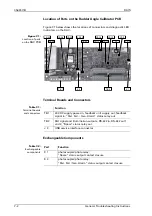
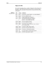
Checks of the on-board supply voltages and I/O signals and data.
The presence of voltages, signals and data is indicated by diagnostic
LEDs on the PCB.
Exact voltage levels must be checked with a voltmeter.
The data content on serial I/O lines must be checked with the aid of
suitable analyzing tools, such as PC-based protocol interpreters or
terminal programs.
•
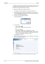
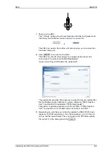
Software-aided troubleshooting using Sperry Marine’s SUSI applica-
tion, if instructed accordingly by Sperry Marine.
DANGER
Life danger through electrical shock
Certain alarm devices may operate with hazardous voltages, switched
by the alarm relay output contacts.
NEVER connect live wires to the unit’s terminals, when wiring up the
Rudder Angle Calibrator.
ALWAYS make sure that any external device or power supply to be con-
nected to the alarm relay outputs is de-energized and safeguarded
against accidental switching-on.
CAUTION
Risk of damage of electrostatic-discharge-sensitive components
The
Rudder Angle Calibrator
contains electrostatic sensitive components.
Electrostatic discharge may permanently damage components.
When configuring the
Rudder Angle Calibrator
, take precautions to prevent
electrostatic discharge. Avoid touching any of the electronic circuitry.
Summary of Contents for Rudder Angle Indicator System
Page 18: ...056357 B RAIS 1 10 Declaration of Conformity...
Page 20: ...056357 B RAIS 2 2 Normal Operational Mode...
Page 26: ...056357 B RAIS 3 6 Viewing RAC Errors through SUSI...
Page 28: ...056357 B RAIS 4 2 Maintenance by Service Personnel...
Page 58: ...056357 B RAIS 7 4 General Troubleshooting Instructions...
Page 64: ...056357 B RAIS 8 6 Replacing Alarm Output Relays...
Page 95: ......
Page 96: ......
Page 97: ......
Page 98: ......
Page 99: ......
Page 100: ......
Page 101: ......
Page 102: ......
Page 103: ......
Page 104: ......
Page 105: ......
Page 106: ......
Page 107: ......
Page 108: ......
Page 109: ......
Page 110: ......
Page 111: ......
Page 112: ......
Page 113: ......
Page 114: ......
Page 115: ......


