


XRM MANUAL
6
118032-001 REV G
WARNING
AFTER TURNOFF, DO NOT HANDLE
THE LOAD UNTIL THE CAPACITANCE
HAS BEEN DISCHARGED!
LOAD CAPACITANCE MAY BE DISCHARGED BY
SHORTING TO GROUND.
WARNUNG
Nach drm Ausschalten des Gerätes die Last erst
berühren wenn diese vollständig entladen ist.
Die elektrische Kapazität der Last kann durch
einen Kurzschluß zur Erde entladen werden.
WARNING
THE VOLTAGE MONITOR ON THE POWER
SUPPLY FRONT PANEL DOES NOT READ THE
OUTPUT VOLTAGE WHEN THE POWER IS
TURNED OFF, EVEN IF A CHARGE STILL
EXISTS ON THE LOAD.
WARNUNG
Der Spannungsmonitor arbeitet nicht bei
abgeschalteter Versorgungspannung, auch nicht
wenn die Last noch aufgeladen ist.
CAUTION
ALWAYS OPERATE THE UNIT WITH THE COVER
ON. DO NOT ATTEMPT TO ACCESS OR REPAIR
ANY INTERNAL CIRCUITS. DANGEROUS AND
LETHAL VOLTAGES ARE GENERATED INSIDE
THE MODULE.
CAUTION
Betreiben Sie das Hochspannungsnetzteil
ausschließlich mit geschlossenem Gehäuse.
Versuchen Sie nicht die internen Schaltkreise zu
berühren oder zu reparieren, da
lebensgefährliche Hochspannungen in Innern
erzeugt werden.
3.2 Standard Features
A note on remote interface circuitry and remote signal
grounding. Whenever possible, electrical isolation should
be provided when interfacing with any high voltage
power supply. For power control signals such as
EXTERNAL INTERLOCK, HIGH VOLTAGE OFF and
HIGH VOLTAGE ON isolated relay contacts should be
used. If possible, analog programming and monitoring
signals should be isolated via analog isolation amplifiers.
Spellman application engineers are available to assist in
interface circuitry design. All interface cables should be
properly shielded. All power supply signals should be
referenced to the power supplies signal ground on J4-1 or
J5-9.
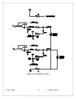
REMOTE PROGRAMMING:
Allows remote
adjustment of the output voltage and current via an
external voltage source. In local control jumpers are
installed on connector J5 in the front of the chassis
between J5-3 and J5-4 for voltage control and between
J5-6 and J5-7 for current control.
For remote programming, the jumpers are removed and a
positive voltage source, from 0 to 10 volts, is applied to
the appropriate terminals. Programming signals should
be referenced to J5-9 signal ground. By adjusting the
voltage source from 0 volts (zero output) to 10 volts (full
rated output) the desired output can be selected. See
Figure 3.4 for wiring diagram and specifications.
An alternate method of controlling the output remotely is
by using external resistance such as a potentiometer or a
resistor network. For remote control the jumpers are
removed and the desired resistor configuration is
installed. See Figure 3.4 for wiring diagram.
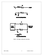
REMOTE MONITOR:
Test points are made available
at J4 on the front of the chassis for monitoring the voltage
and current output. The test points are always positive
regardless of the output polarity, where zero 0 to 10 volts
equals 0-100% of output. Test points have an output
impedance of <10 ohms. See Figure 3.3 for test point
designation.
EXTERNAL INTERLOCK:
Interlock connections are
provided on J4-4 on the front of the chassis for
connection to a safety switch. The unit will not operate
unless the interlock circuit is closed. During high voltage
operation, opening the interlock circuit will cause the unit
to revert to the HIGH VOLTAGE OFF mode. See Figure
3.3 for the recommended interface circuit.


