


UM MANUAL
3
118098-001 REV B
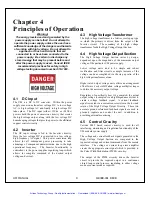
Chapter 2
I
NSPECTION
&
I
NSTALLATION
nitial inspection and preliminary checkout procedures
are recommended. For safe operation, please follow
the procedures described in Chapter 3, Operating
Instructions.
2.1 Initial Inspection
Inspect the packaging exterior for evidence of damage
due to improper handling in transit. Notify the carrier and
Spellman High Voltage immediately if damage is evident.
Do not destroy or remove any of the packing material
used in a damaged shipment.
After unpacking inspect the power supply for any visible
signs of damage.
2.2 Mechanical Installation
Standard UM modules are intended for direct printed
circuit board mounting, it is recommended that the unit be
processed in a hand solder operation only.
Solder iron tip temperatures are most commonly between
315-371°C (600-700°F) for Sn63/Pb37 alloys and
between 371-427°C (700-800°F) for Sn96.5/Ag3.0/Cu0.5
lead-free alloys.
Heat both the land area and component lead to be
soldered with the iron prior to adding cored wire. Apply
the solder wire to the land area or component lead. Do
not apply the wire directly to the soldering iron tip. Do
not apply solder iron to joint for a period exceeding 15
seconds.
Process and inspect workmanship to IPC-A-610 class 2
standards as applicable.
Two 2-56 pan head stainless steel screws are provided to
mechanically secure the unit to the printed circuit board
assembly. Tighten the screws to 3 inch/pounds
(0.34N•m) of torque.
Do not use longer screws than those provided, otherwise
risk of damage to the unit is possible. The mounting
screws are electrically isolated, they are not connected to
any potential or ground point inside the power supply.
Please see the UM data sheet for a more detailed
dimensional drawing.
2.3 Cooling Considerations
Convection cooled, typical. 30 watt units operating at full
power might require additional cooling to maintain case
temperature below 65°C. Methods may include: forced
air cooling, use of heat sink or metal case, etc. It is the
user’s responsibility to maintain case temperature below
65°C. Damage to the power supply due to inadequate
cooling is considered misuse and repairs will not be
covered under warranty.
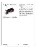
Adhesive Backed Heat Sink
UM modules are provided with an uninstalled top
mounted adhesive backed heat sink. Label removal is not
required if the customer elects to install and use the
provided heat sink.
The UM’s internal power dissipation causes the case
temperature to rise. If the case exceeds 65°C, the unit
needs external cooling (fan or heat sink). Even if the case
is below 65°C, it is prudent to keep it much lower. Like a
semiconductor device; the hotter it is, the shorter the
lifetime will be increased by a factor of
≈
2.35. The
thermal resistance from internal circuitry to ambient is
8°C/watt without a heat sink (still air). This reduces to
6°C/watt with the heat sink.
I
Artisan Technology Group - Quality Instrumentation ... Guaranteed | (888) 88-SOURCE | www.artisantg.com


