

81317-4r1 MXR20PN24 & MXR30PN24 Installation & User Guide
9 of 10
2.
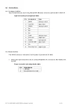
Control connections are via a 10 way ‘IDC Ribbon cable’ connector.
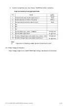
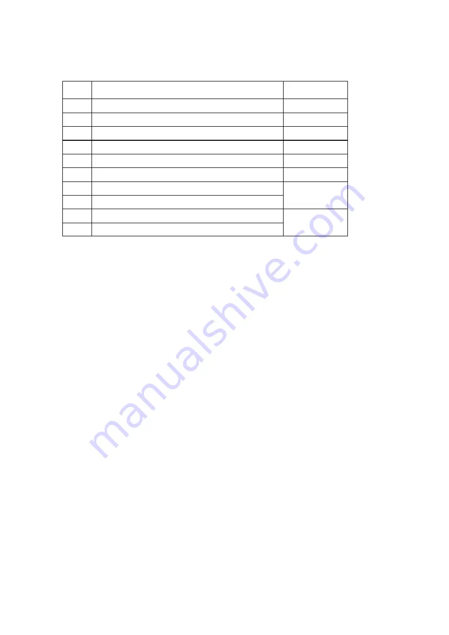
Input connector pin assignments table
Pin
Signal
Level/
Range
1
Transmit data (output) with respect to pin 2
Serial
2
Serial signal ground return (if required)
RTN (i)
3
Receive data (input) with respect to pin 2
Serial
4
NC
5
NC
6
NC
7
Opto-isolator input
– [0mA = INHIBIT]
3V3 @ 6mA
5V @ 10mA
8
Opto-isolator signal return
9
Polarity Change Signal opto-isolator input - [0mA = -VE]
3V3 @ 6mA
5V @ 10mA
10
Polarity Change Signal opto-isolator signal return
Note:
(i)
Take care in choosing suitable ground connection for pin 2.
3.4.3 High Voltage Connection
High Voltage output is via a GES HB30 high voltage receptacle for all versions.