background image

600 SERIES MANUAL  

118118-001 Rev A 

SECTION IV – CIRCUIT DESCRIPTION 
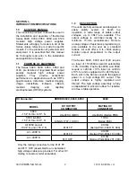
4.1 FUNCTIONAL DESCRIPTION

The 602C, 603C, and 612C employ a standard 
step-down transformer to obtain a nominal 
+28Vdc from the input ac power. The Series 
605C and 606C 28Vdc (+24Vdc for 
+24V Option models) from the input ac power. 
The circuit converts the +Vdc low voltage input 

DC power to a high voltage DC output. This 
output voltage is highly regulated and filtered and 
can be varied either by the local potentiometer 
control or through the REMOTE PROGRAM 
input. 

An oscillator determines the frequency 
(approximately 20kHz) at which all 
amplification, high voltage transformation, 
rectification and filtering occurs. The 
amplification is a function of a control voltage 
which performs the function of control and 
regulation. A sample of the output voltage is 
compared against a reference voltage in the 
sensing circuit. The sensing circuit generates 
the control voltage to set and maintain a fixed 
high voltage output. 

The encapsulated high voltage assembly 
includes a high voltage power transformer, 
rectifier or multiplier circuits, ripple filter and 
sensing circuits. These are all critical, custom 
designed and encapsulated components. 

SECTION V – MAINTENANCE 
5.1 GENERAL

The high voltage power supply should not 
require any maintenance or calibration. It is 
designed for reliable, trouble free operation. If 
any question should arise, contact the Bertan 
Customer Service Department for assistance or 
return authorization. Although it is felt that 
adequate information is provided in this 
manual, it is suggested that the unit be 
returned to the factory is service should 
become necessary. 

The power supply can be returned to the 
factory for annual calibration and certification to 
its original specification. For traceability, a 
certificate will be issued, identifying the serial 
number of the unit calibrated and all test 

equipment used to perform the calibration. All 
measurements are traceable to the National 
Institute of Standards and Technology 
(N.I.S.T.). Contact the factory for additional 
details. 

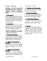
5.2 CLEANING

Cleaning of the power supply should 

only

be 

performed with the supply disconnected from 
the ac power source. A soft cloth moistened 
with conventional ammonia-based cleaning 
agents will suffice for all exposed surfaces. The 
exposed shell of the HV connector should be 
cleaned with isopropyl alcohol. 

If the supply is operated in a dusty 
environment, an accumulation of dust/debris 
may build-up inside the unit which may cause 
noisy operation (i.e., “ticking” or minor 
crackling) in the area of the HV cabling on the 
10kV through 30kV models. The safest way to 
remove such debris is with compressed air. 
Ensure that no dust/debris is left behind in the 
insulative medium of the HV output connector 
after this cleaning operation. Such dust may be 
removed with a cotton swab moistened with 
isopropyl alcohol. 

Summary of Contents for BERTAN 602C-100N

Page 1: ...117 001 Rev A R Instruction Manual SPELLMAN HIGH VOLTAGE ELECTRONICS CORPORATION One Commerce Park Valhalla New York 10595 1 914 686 3600 FAX 1 914 686 5424 E mail sales spellmanhv com Website www spellmanhv com 600 SERIES ...

Page 2: ...y 0 01 per hour after a 1 2 hour warm up Accuracy Local control 0 2 Remote Programming 0 1 of setting 0 1 of maximum Voltage Monitor 0 1 of reading 0 1 of maximum Current Monitor 2 of reading 1 of maximum Temperature Coefficient 50ppm C Arc Short Circuit All units are fully arc and short circuit protected and will limit continuous short circuit output current to less than 110 of maximum rated outp...

Page 3: ... Trip Input Connect to ground to trip unit off 9 Local Voltage Program Internal program potentiometer wiper 0 to 5Vdc Terminal Function 1 115 230 Vac Input 2 Neutral 3 Ground PAGE 2 OF 2 TOP VIEW BOTTOM VIEW FRONT VIEW REAR VIEW HV ADJUST P2 115V 230V FUSE HV OUT LINE NEUT GND 8 32 UNC 2B 25 MAX DP 3PL 1 00 5 0 5 03 127 62 5 0 42 10 6 7 62 193 3 06 77 7 2 12 53 8 1 53 38 8 1 06 26 9 5 75 146 DIMEN...

Page 4: ...ity 0 01 per hour after a 1 2 hour warm up Accuracy Local Control 0 2 Remote Programming 0 1 of setting 0 1 of maximum Voltage Monitor 0 1 of reading 0 1 of maximum Current Monitor 2 of reading 1 of maximum Temperature Coefficient 50ppm C Arc Short Circuit All units are fully arc and short circuit protected and will limit continuous short circuit output current to less than 110 of maximum rated ou...

Page 5: ... 0 to 5Vdc 0 to 100 rated output 10KΩ Zout 8 Trip Input Connect to ground to trip unit off 9 Local Voltage Program Internal program potentiometer wiper 0 to 5Vdc TOP VIEW BOTTOM VIEW FRONT VIEW REAR VIEW HV ADJUST P2 115V 230V FUSE HV OUT LINE NEUT GND 8 32 UNC 2B 31 MAX DP 3PL 5 00 127 7 50 190 40 10 44 11 6 40 162 78 19 8 1 00 25 4 4 00 101 2 34 59 4 5 50 139 AC INPUT TERMINAL BLOCK Terminal Fun...

Page 6: ...full load change Ripple See model ratings table Stability 0 01 per hour after a 1 2 hour warm up Accuracy Local control 0 2 Remote Programming 0 1 of setting 0 1 of maximum Voltage Monitor 0 1 of reading 0 1 of maximum Current Monitor 2 of reading 1 of maximum Temperature Coefficient 50ppm C Arc Short Circuit All units are fully arc and short circuit protected and will limit continuous short circu...

Page 7: ... Input 28Vdc Power Input 24Vdc optional 3 Signal Ground Signal Ground 4 Voltage Program 0 to 5Vdc 0 to 100 rated output 1MΩ Zin 5 5 0Vdc Reference 5 0Vdc 10mA maximum 6 kV Monitor 0 to 5Vdc 0 to 100 rated output 10KΩ Zout 7 mA Monitor 0 to 5Vdc 0 to 100 rated output 10KΩ Zout 8 Trip Input Connect to ground to trip unit off 9 Local Voltage Program Internal program potentiometer wiper 0 to 5Vdc S P ...

Page 8: ...ratings table Stability 0 01 per hour after a 1 2 hour warm up Accuracy Local control 0 2 Remote Programming 0 1 of setting 0 1 of maximum Voltage Monitor 0 1 of reading 0 1 of maximum Current Monitor 2 of reading 1 of maximum Temperature Coefficient 50ppm C Arc Short Circuit All units are fully arc and short circuit protected and will limit continuous short circuit output current to less than 110...

Page 9: ...P N 0 to 1 5kV 0 to 20mA 15mV 606C 30P N 0 to 3kV 0 to 10mA 30mV 606C 50P N 0 to 5kV 0 to 5mA 50mV 606C 100P N 0 to 10kV 0 to 2mA 200mV 606C 150P N 0 to 15kV 0 to 1 5mA 450mV 606C 200P N 0 to 20kV 0 to 1 0mA 800mV 606C 300P N 0 to 30kV 0 to 0 4mA 6 volts S P E L L M A N H I G H V O LTA G E E L E C T R O N I C S C O R P O R AT I O N HIGH VOLTAGE MODULE 606C TOP VIEW BOTTOM VIEW FRONT VIEW REAR VIEW...

Page 10: ... aware of the electrical hazards WARNING note in the text call attention to hazards in operation of these units that could lead to possible injury or death CAUTION notes in the text indicate procedures to be followed to avoid possible damage to equipment Copyright 2000 Spellman High Voltage Electronics Corporation All Rights Reserved This information contained in this publication is derived in par...

Page 11: ...spannungsnetzteiles benötigen ca 5 Minuten um sich zu entladen Erden Sie sich nicht und arbeiten Sie nicht in feuchter oder nasser Umgebung Notwendige Reparaturen können es erforderlich machen den Gehäusedeckel während des Betriebes zu entfernen Reparaturen dürfen nur von qualifiziertem eingewiesenem Personal ausgeführt werden WARNING im folgenden Text weist auf gefährliche Operationen hin die zu ...

Page 12: ...de l alimentation Ne vous mettez pas à la masse ou ne travaillez pas sous conditions mouillées ou humides La maintenance peut nécessiter l enlèvement du couvercle lorsque l alimentation est encore allumée Les réparations doivent être effectuées par une personne qualifiée et connaissant les risques électriques Dans le manuel les notes marquées WARNING attire l attention sur les risques lors de la m...

Page 13: ...carica della capacità interna dell alimentatore ad alta tensione Non mettere a terra il proprio corpo oppure operare in ambienti bagnati o saturi d umidità SICUREZZA NELLA MANUTENZIONE Manutenzione potrebbe essere richiesta rimuovendo la copertura con apparecchio acceso La manutenzione deve essere svolta da personale qualificato coscio dei rischi elettrici Attenzione alle AVVERTENZE contenute nel ...

Page 14: ...tentiometer Control 4 2 3 3 External Voltage Control 4 2 4 High Voltage Monitor 4 2 5 Output Current Monitor 4 2 6 Trip Unit 4 2 7 Input Control Monitor Connections 5 III PROGRAMMING OPTIONS 3 1 General 5 3 2 Standard Mode 6 3 3 5 Volt Programming Mode for 0 100 output voltage 6 3 4 5 Volt Programming Mode for 0 103 output voltage 6 3 5 Series 612C 5 Volt Programming Mode 6 IV CIRCUIT DESCRIPTION ...

Page 15: ...The output voltage is controlled locally by a minimum 15 turn potentiometer Remote analog voltage of resistance programming is also available to the user as a standard feature All units offer a 0 to 5Vdc analog monitor output proportional to the output current The Series 602C 603C and 612C require an input of 115 230Vac switch selectable 10 50 60Hz The Series 605C and 606C require a 28Vdc 10 input...

Page 16: ... 612C MODEL HV OUTPUT MATING HV CONNECTOR CONNECTOR KIT 612C 200 JJA 405787 612C 300 JJA 405787 612C 500 JJB 405786 SERIES SIZE H x W x D mm WEIGHT Lbs kg 602C 5 03 x 3 06 x 8 66 6 75 1 25 x 78 x 220 3 1 603C 5 00 x 5 50 x 8 50 8 0 127 x 140 x 216 3 64 605C 5 04 x 2 75 x 4 75 3 2 128 x 70 140 x 114 1 45 606C 5 00 x 5 50 x 4 50 3 5 127 x 140 x 114 1 6 612C 4 88 x 8 38 x 9 75 9 124 x 213 x 248 4 1 ...

Page 17: ...IOMETER CONTROL See Section 2 7 for hook up information This will allow control of the high voltage output by means of the multi turn potentiometer accessible via a hole in the cover 2 3 2 EXTERNAL POTENTIOMETER CONTROL See Section 2 7 for hook up information Connecting an external potentiometer recommended value of 5kW will control the high voltage output independently of the internal potentiomet...

Page 18: ...4 to pin 9 For remote potentiometer control connect the remote potentiometer as follows CW terminal to P2 pin 5 CCW terminal to P2 pin 3 Wiper terminal to P2 pin 4 For remote 0 to 5V voltage programming apply the input program voltage to P2 pin 4 For remote TRIP connect P2 pin 8 to P2 pin 3 SECTION III PROGRAMMING OPTIONS 3 1 GENERAL To provide additional flexibility and compatibility with earlier...

Page 19: ...s applied to P2 pin 4 same as for Standard Mode No jumpers should be attached to P2 the external connector In this mode the internal potentiometer is used to control the maximum programmed output voltage at 5 Volt programming input With the potentiometer fully clockwise the output will be 0 to 103 of maximum for a 0 to 5 Volt input With the potentiometer turned up approximately half way a 0 to 5 V...

Page 20: ...OGRAMMING for 0 to 103 output voltage MODE Jumper pins 1 to 2 pins 3 to 5 and pins 6 to 8 3 5 ERIES 612C 5 VOLT PROGRAMMING MODE Jumper pins 3 to 5 pins 4 to 6 and pins 7 to 8 TABLE III 2 J3 PIN CONNECTIONS Series 612C Option 5VPRO only PIN A 0 to 5Volt programming input PIN B NC PIN D Output voltage monitor 0 to 5V for 0 to maximum HV output PIN E GND PIN H Output current monitor 0 to 5V for 0 to...

Page 21: ...or reliable trouble free operation If any question should arise contact the Bertan Customer Service Department for assistance or return authorization Although it is felt that adequate information is provided in this manual it is suggested that the unit be returned to the factory is service should become necessary The power supply can be returned to the factory for annual calibration and certificat...

Page 22: ...ged breach of this warranty No modification amendment supplement addition or other variation of this warranty will be binding unless it is set forth in a written instrument signed by an authorized officer of Spellman Factory Service Procedures For an authorization to ship contact Spellman s Customer Service Department Please state the model and serial numbers which are on the plate on the rear pan...

Reviews: