136
M3i.48xx / M3i.48xx-exp Manual
Details on M3i cards I/O lines
Details on M3i cards I/O lines
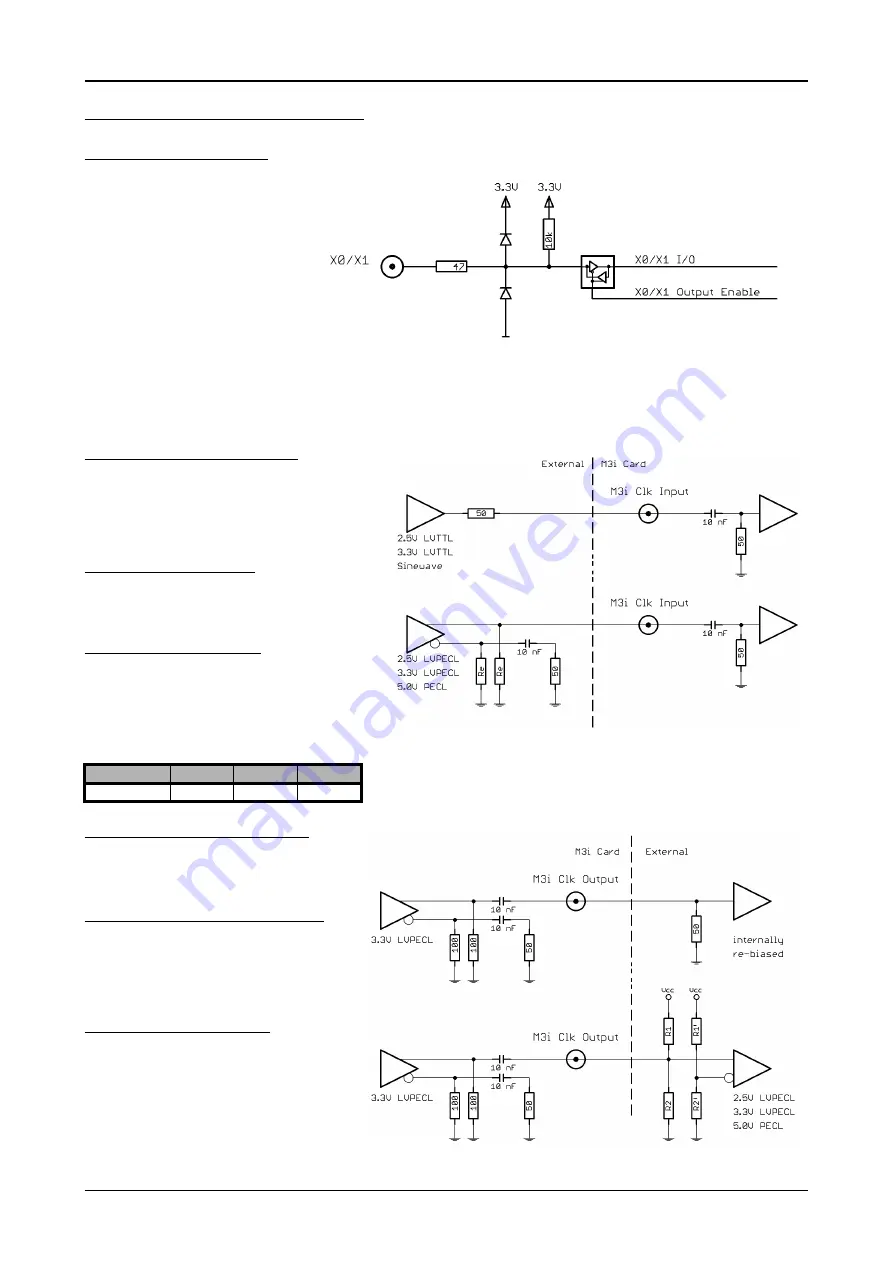
Multi Purpose I/O Lines
The MMCX Multi Purpose I/O connec-
tors (X0 and X1) of the M3i cards from
Spectrum are protected against over
voltage conditions.
For this purpose clamping diodes of the
types 1N4148 are used in conjunction
with a series resistor. Both I/O lines are
internally clamped to signal ground and
to 3.3V clamping voltage. So when con-
necting sources with a higher level than
the clamping voltage plus the forward
voltage of typically 0.6..0.7 V will be
the resulting maximum high-level level.
The maximum forward current limit for the used 1N4148 diodes is 100 mA, which is effectively limited by the used series resistor for logic
levels up to 5.0V. To avoid floating levels with unconnected inputs, a pull up resistor of 10 kOhm to 3.3V is used on each line.
Interfacing with clock input
The clock input of the M3i cards is AC-coupled, single-
ended PECL type. Due to the internal biasing and a rela-
tively high maximum input voltage swing, it can be di-
rectlly connected to various logic standards, without the
need for external level converters.
Single-ended LVTTL sources
All LVTTL sources, be it 2.5V LVTTL or 3.3V LVTTL must be
terminated with a 50 Ohm series resistor to avoid reflec-
tions and limit the maximum swing for the M3i card.
Differential (LV)PECL sources
Differential drivers require equal load on both the true
and the inverting outputs. Therefore the inverting output
should be loaded as shown in the drawing. All PECL driv-
ers require a proper DC path to ground, therefore emitter
resistors R
E
must be used, whose value depends on the
supply voltage of the driving PECL buffer:
Interfacing with clock output
The clock output of the M3i cards is AC-coupled, sin-
gle-ended PECL type. The output swing of the M3i
clock output is approximately 800 mV
PP
.
Internal biased single-ended receivers
Because of the AC coupling of the M3i clock output,
the signal must be properly re-biased for the receiv-
er. Receivers that provide an internal re-bias only re-
quire the signal to be terminated to ground by a
50 Ohm resistor.
Differential (LV)PECL receivers
Differential receivers require proper re-biasing and
likely a small minimum difference between the true
and the inverting input to avoid ringing with open re-
ceiver inputs. Therefore a Thevenin-equivalent can
be used, with receiver-type dependant values for
R1, R2, R1’ and R2’.
V
CC
- V
EE
2.5 V
3.3 V
5.0 V
R
E
~50 Ohm
~100 Ohm
~200 Ohm


