0191446R1 Page 2 of 3
8-32 x 1/2” PH
thread-cutting screw
(3 required per slide)
Figure 2.1
Keyboard T
ray
Inner
slide
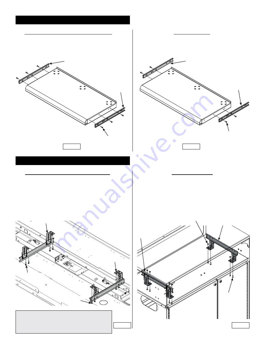
2. Attach inner slides to tray
2. Attach inner slides to tray
1. Attach each inner left and right slide to the keyboard tray with (3) 8-32
x 1/2” PH thread-cutting screws and tighten securely.
Figure 2.1
Freedom XRS / CORE Lecterns:
Pivot Premier
Figure 2.2
Keyboard T
ray
8-32 x 1/2” PH
thread-cutting screw
(2 required per slide)
Inner
slide
1. Slides mounted in rear position. Attach each inner left and right slide
to the keyboard tray with (2) 8-32 x 1/2” PH thread-cutting screws
and tighten securely.
Figure 2.2
3. Install slide assemblies
3. Install slide assemblies
1. Determine the preferred position of the keyboard tray (left center right).
Pre-drilled mounting holes are available for multiple mounting locations.
2. Attach each outer slide assembly to the underside of the worksurface
with (4) #8 x 5/8” PHSM screws but do not tighten completely.
(Brackets face inward).
Figure 3.1
.
3. Tighten screws on one slide assembly only-leave the screws on the
other slide assembly slightly loose.
Note: The lecterns have pre-drilled holes in left, center, and
right positions for keyboard tray mounting.
On Freedom XRS Lecterns, the keyboard tray should be in-
stalled on the side opposite the equipment rack (if equipped).
Figure 3.2
(4) #8 x 5/8”
PHSM
Outer slide
assembly
Outer slide
assembly
Worksurface
Inner
slide
Inner
slide
1. Align and attach the left and right slide assemblies with 8-32 x 1/2”
PH thread-cutting screws, but do not tighten completely.
Figure 3.2
.
Mid-panel
Slide assembly
(right)
Slide assembly
(left)
8-32 x 1/2” PH
thread-cutting
screw
(2 per bracket)
8-32 Locknut
(2 per bracket)
Freedom XRS / Pivot Premiere:
CORE Lectern:
(4) #8 x 5/8”
PHSM
Figure 3.1


