Chapter 3: Configuring the 2085-IT8-SC/IT-16-SC Using CCW
3-33
User’s Manual Pub. 0300322-01 Rev. A
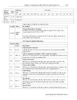
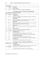
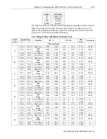
data ready for channel CJ compensation, these bits will be cleared, and the
channel input reading will be resumed.
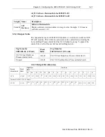
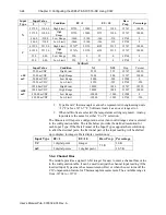
Estimated channel scan rates are:
ADC
Filter
Selection
MUX/PGA
Settling
Time
ADC
Conversion
Time
MCU
Processing
Overhead
Total Channel Scan Rate
Measurement per
Channel*
17 Hz
10
121
8
139
4 Hz
10
481
8
499
62 Hz
10
33
8
51
470 Hz
10
5
8
23
NOTE:
•
All timing units are in ms.
•
*: Channel configuration setup for 1 measurement only. This applies to
all Input Types.
•
The second measurement on open circuit detection occurs every 3
seconds which will take 23 ms per enabled channel.
Module update rate is proportional to the channels enabled and it is also affected
by the open circuit detection enable bits. The following table indicates maximum
module date rate with all channels enabled, and all channel open circuit detection
bits enabled.
ADC
Filter
Selection
Scan Rate
Per
Channel
Number of
Channels
Total Module Scan Rate
17 Hz
139 + 23
16
1296
4 Hz
499 + 23
16
4176
62 Hz
51 + 23
16
592
470 Hz
23 + 23
16
368
3.9.1
Module Specific Hardware Errors
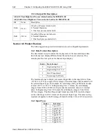
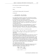
A Micro850 or 870 PLC can generate a series of 0×F2
xy
error codes specific to
an Expansion I/O module. The Fault code is 0×F29
z
, where z indicates the slot
number of the expansion I/O. If z=0, then the slot number cannot be identified.
Fault Code
Extended Fault Code
Combined
Error Description
xF29z*
0×302
0×302
MCU board power brownout
0×303
0×303
Unused
0×304
0×304
A/D Converter Communication Error.
Module detects the analog-to-digital
converter is not functioning properly
during data acquisition.
*: z indicates the slot number of the expansion I/O. If z=0, then the slot number cannot be
identified.
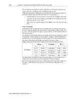
Example error captured below.

