background image


Service Manual ProTone 

Page 4 of  20 

© 1996-2001 Spectral Audio 

TUNE

PW

NOISE

TUNE

SLIDE

EXT

VCO 1

VCO 2

FILTER

KEY-

FOLLOW

LFO

FREQUENCY

MODULATION

WAVE

LFO ON ...

NOISE

EXT.

PW 1

VCO 1

VCO 2

PAN

RANDOM

RANGE

MIDDLE

LOW

HIGH

ProTone

GATE /

LEARN

POWER

GROUND-

LEVEL

LEARN

PAN

ENV MOD

CUTOFF

RESONANZ

VOL VCO 2

RINGMOD

VOL VCO 1

DECAY

ATTACK

SUSTAIN

RELEASE

CUT

OFF

ACCENT

24 dB

HIGHPASS

LOWPASS

12 dB

SYNC

ON

MIDI ANALOG SYNTHESIZER

-

6

5

4

2

1

12

3

0

78

9

10

11

6

5

4

2

1

12

3

0

78

9

10

11

6

5

4

2

1

12

3

0

78

9

10

11

6

5

4

2

1

12

3

0

78

9

10

11

6

5

4

2

1

12

3

0

78

9

10

11

6

5

4

2

1

12

3

0

78

9

10

11

6

5

4

2

1

12

3

0

78

9

10

11

6

5

4

2

1

12

3

0

78

9

10

11

6

5

4

2

1

12

3

0

78

9

10

11

6

5

4

2

1

12

3

0

78

9

10

11

6

5

4

2

1

12

3

0

78

9

10

11

6

5

4

2

1

12

3

0

78

9

10

11

6

5

4

2

1

12

3

0

78

9

10

11

6

5

4

2

1

12

3

0

78

9

10

11

6

5

4

2

1

12

3

0

78

9

10

11

6

5

4

2

1

12

3

0

78

9

10

11

C1

R

L

5

4

3

2

5

1

4

3

2

0 1

6

6

5

4

3

2

5

1

4

3

2

-

+

0 1

6

6

5

4

3

2

5

1

4

3

2

-

+

1

0

1

2

3

4

5

6

7

8

9

11

14

10

12

13

18

19

15

16

17

25

26

27

20

21

22

23

24

28

29

31

30

32

33 34

35

SPECTRAL AUDIO


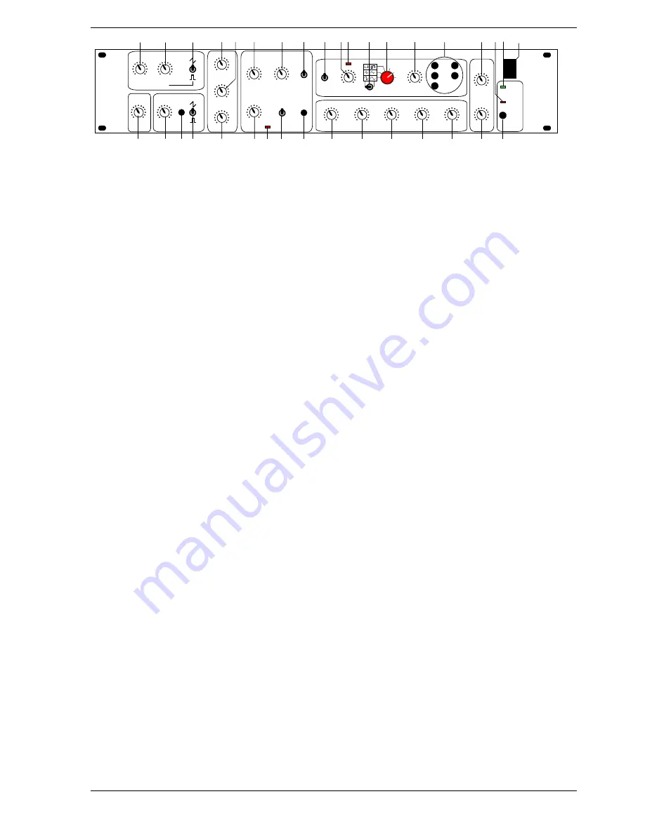
1.2   Front Panel Controls 

 
VCO 1: 

1.  TUNE: Regulates the pitch of the VCO 1 
2.  PW: Pulse width of the rectangular pulse 
3.  Changeover between the signal types saw tooth, noise and rectangle 
4.  SLIDE: regulates the time balance of VCO 1 and VCO 2 

VCO 2: 

5.  TUNE: Regulates the pitch of the VCO 2 
6.  SYNC: Synchronises VCO 2 with VCO 1 
7.  Changeover between the signal types saw tooth, external (input on rear of housing) and rectangle 

Mixer: 

8.  VOL VCO 1: Volume of VCO 1 
9.  RINGMOD: Volume of the ring modulation of VCO1 and VCO2 
10.  VOL VCO 2: Volume of VCO 2 

VCF: 

11.  CUTOFF: Cut-off frequency of the filter 
12.  RESONANCE: increases the harmonics at the cut-off point 
13.  Changeover between lowpass and highpass 
14.  ACCENT: Pulsed increase of the cut-off frequency and the volume 
15.  ACCENT ON Indicator: Lights when the accent function is switched on (MIDI Controller 65) 
16.  Determines the edge steepness of the filter: 12  or 24dB / octave 
17.  KEYFOLLOW: The cut-off frequency is influenced by the actual note 

LFO: 

18.  RANGE: Changeover between three LFO frequency ranges 
19.  FREQUENCY: Setting the LFO frequency 
20.  LFO Indicator: Indicates each positive half wave of the LFO.  
 

Note:

  The eye recognises frequencies larger than 60 Hz as being static. 

21.  Changeover between symmetrical and asymmetrical LFO waveforms 
22.  Selector switch for different LFO waveforms. By means of the matrix presentation, there are a total of 9 

signal forms available: sinus, asymmetrical sinus, triangle, saw tooth, rectangle, pulse, random, noise and 
external (input on the rear of the housing) 

23.  MODULATION: Determines the strength of the LFO influence 
24.  LFO ON..: LFO assignment possibilities: VCO 1, VCO 2, PW 1, cut-off, pan (any combination possible) 

Envelope: 

25.  ATTACK: Rise time  
26.  DECAY: Decay time 
27.  SUSTAIN: Hold level 
28.  RELEASE: Release time 
29.  ENV MOD: Influences the cut-off frequency with the envelope 

Stereo VCA: 

30.  GROUNDLEVEL: Ground level of the unit. This also includes the volume increase influenced by the 

accent. 

31.  PAN: Regulates the relationship of the volume from the left and right-hand channel 

Various:


32.  LEARN Key; Switches the ProTone to the learn mode 
33.  GATE / LEARN indicator 
34. Switch-on indicator 
35. Main switch 

Summary of Contents for ProTone

Page 1: ...yright 1996 2001 by Spectral Audio Switzerland CAUTION All instructions in this manual must be carried out by a professional who observes the valid safety regulations In operation they have got danger...

Page 2: ...ements and explanations 7 4 1 Sense of R174 and R175 7 4 2 Sense of C63 C65 7 4 3 Sense of R174 and R175 8 4 4 Hum Problems 8 4 5 Increasing the Gate voltage to 12V 8 5 Adjustment of the ProTone 9 5 1...

Page 3: ...icht ffnen Avis Risque de choc Electrique ne pas ouvrir SPECTRAL AUDIO GmbH Serial No 1 1 Sockets on the Rear of the Housing 36 Power socket 37 Fuse compartment fuse max 500 mA 250V type 38 Audio outp...

Page 4: ...f VCO 1 9 RINGMOD Volume of the ring modulation of VCO1 and VCO2 10 VOL VCO 2 Volume of VCO 2 VCF 11 CUTOFF Cut off frequency of the filter 12 RESONANCE increases the harmonics at the cut off point 13...

Page 5: ...s remain the same The resonance forms a feedback of the output to the input of the filter and causes an amplification of the frequencies around the cut off frequency The ACCENT regulator 14 sets the s...

Page 6: ...ce Manual ProTone Page 6 of 20 1996 2001 Spectral Audio released The parameters of the envelope can be set with regulators 25 to 28 How the envelope should be imagined is described later on in the glo...

Page 7: ...ectral Audio may send it to you for important reasons please write to info spectralaudio ch 4 Improvements and explanations 4 1 Sense of R174 and R175 These two resistors helps to increase the lower l...

Page 8: ...internal connection from GND to the metal case creates a hum noise because of closed earth loops In this case it may help to cut this internal GND connection You will find it on later Proton s series...

Page 9: ...hapter above The setting of R10 in the MIDI to CV converter is valid for both VCO of course 5 2 1 VCO1 The frequency of the oscillator can be taken from pin 8 of U11 or at the unit output whereby the...

Page 10: ...ncy meter 11 Press key A1 and set the frequency to 55 00 Hz with R156 12 Repeat steps 3 and 4 until frequency values are stable 13 Press the key A5 and set the frequency to 880 0 Hz with R132 Check he...

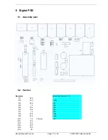
Page 11: ...Spectral Audio 6 Digital PCB 6 1 Assembly plan 6 2 Part list Resistors Metal Film Resistor 1 R1 220 R2 220 100R R3 220 4k7 R4 1k 24k R5 10k 30k R6 10k 62k R7 1k 91k R8 47k 100k R9 47k 300k R10 2k Tri...

Page 12: ...54 2 x 5 C56 10u Elko 2 d 5 C66 2 2u Elko 2 d 5 C67 2 2u Elko 2 d 5 Semiconductors Q1 TL 431 CLP D1 1N4148 D2 1N4148 D3 1N4148 D4 DF 02 M D13 1N4148 U1 CNY17 3 SFH 601 3 U2 TL 074 CN U3 24C01 02 CB U4...

Page 13: ...e Manual ProTone Page 13 of 20 1996 2001 Spectral Audio W1 Plug Ledge 3 pole W2 Plug Ledge 3 pole Jump1Jumper 2 54 mm assemble on W1 Out Jump2Jumper 2 54 mm assemble on W2 Out 7 Analog PCB 7 1 Assembl...

Page 14: ...Service Manual ProTone Page 14 of 20 1996 2001 Spectral Audio...

Page 15: ...R23 100K R24 100K R25 100K R26 10K R27 15K R28 1K R29 10K Trimmer R30 4K7 R31 10K R32 1M R33 1M R34 300K R35 2K2 R36 390 R37 2K2 R38 470 R39 220 R40 10K R41 1K R42 91K R43 15K R44 10K R45 91K R46 10K...

Page 16: ...9 100K R80 220K R81 5k1 R82 100 R83 1M R84 1M R85 100 R86 5k1 R87 10K R88 10K R89 100K R90 180K R91 470K R92 2M2 R93 470 R94 2M2 R95 220K R96 220K R97 24K R98 300K R99 62K R100 24K R101 300K R102 470K...

Page 17: ...R144 470 R146 15K R147 1K R148 1K R149 4K7 R150 10K R151 24K R152 300K R153 10K R154 47K R155 100 R156 1K Trimmer R157 1K Trimmer R158 30K R159 1K R160 470K R162 470 R163 15K R164 1K R165 1K R166 24K...

Page 18: ...C24 4p7 Ker 2 54 1 8 x 3 5 Philips C25 1u Foil 5 6 x 10 5 EVOX C26 47n Foil 5 2 5 x 7 2 EVOX C27 470p Foil 5 2 5 x 7 2 WIMA C28 470p Foil 5 2 5 x 7 2 WIMA C29 47n Foil 5 2 5 x 7 2 EVOX C30 100n Ker 2...

Page 19: ...Q25 BC 556 B Q26 BC 556 B D7 1N4148 D8 1N4148 D9 1N4148 D10 1N4148 D11 1N4148 D12 1N4148 D14 1N4148 D15 1N4148 D16 1N4148 DL1 2 5 x 5mm Green Assemble with 8 mm spacer Total 17mm DL2 2 5 x 5mm Red As...

Page 20: ...1 EE 1 pole on off Push Push Switch ITT S15 PVA1 OA 1 pole on off Momentary Switch ITT SW1 56P36 01 1 06N 6 pole Rotary Switch Grayhill J12 Connector 18 pole Socket mounted on Solder Side 8 Mechanical...

Reviews: