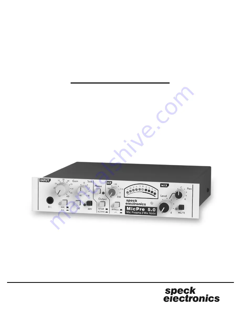
MicPre 5.0
Microphone Preamp & Mix Node
Reference Manual
Page 1: ...MicPre 5 0 Microphone Preamp Mix Node Reference Manual...
Page 2: ......
Page 3: ...California 92028 If in our opinion the packing container is improper for return shipping we reserve the right to supply a new container at a minimal charge In the interest of improving Speck products...
Page 4: ...Link Connector Connecting the MP 5 0 to the ASC Equalizer Interfacing two MP 5 0 s Interfacing more than two MP 5 0 s Interfacing two MP 5 0 s for M S operation General Default control settings Signal...
Page 5: ...fications General Start simple Audio Cable Connectors AC Distribution and safety Proper AC grounding Quality AC system AC distribution Clock noise and AC Safety earth connection Audio earth Proper aud...
Page 6: ...v...
Page 7: ...re 5 0 will also be referred to as the MP 5 0 The signal path consists of a matched discrete transistor front end premium IC s and transformer output stage With the push of a button the MP 5 0 can cha...
Page 8: ...upply power to the Model ASC equalizer P N ASC DCI 1U rack tray may be used to rack mount two MP 5 0 s or one MP 5 0 and one Model ASC equalizer The MP 5 0 is intended to operate from an AC power sour...
Page 9: ...e MP 5 0 without the cover properly installed The MP 5 0 with its internal power supply contains voltages that can cause serious injury or death Refer all repairs to a qualified service technician or...
Page 10: ...Chapter 1 Introduction Section 4 This page left intentionally blank...
Page 11: ...will prolong component life and maximize operational stability To insure adequate airflow around the unit and to prevent overheating we recommend leaving a 1U blank panel above and below the MP 5 0 an...
Page 12: ...uld be secured with the 2 6 32 x machine screws supplied with the unit Do not use screws that are longer than in length as they could damage the internal circuit board When the MP 5 0 or multiple MP 5...
Page 13: ...dentifying the owner and indicating the service or repair to be accomplished Include the model number and serial number of the product Place the product in the original container if available If the o...
Page 14: ...right output terminals on the mix link connector The active balanced TRS insert jacks serve a secondary function on the MP 5 0 The Insert Send may be used as an additional balanced Pre Out B 3 and the...
Page 15: ...e 2 The Mix Link connector 6 is a RJ45 modular jack that allows the mix section of the MP 5 0 to be combined with additional MP 5 0 s The terminals on the mix link connector include the left right mix...
Page 16: ...t the other end of the interface cable green mark face up to the connection marked Aux DC I O on the ASC The plugs and respective connectors are keyed so they will fit in only one direction USE WITH S...
Page 17: ...link two MP 5 0 s Linking two MP 5 0 s DIRECT OUTPUT INPUT MIX LINK speck electronics S N 230V 1A MIX LEFT INSERT RTN PRE OUT B INSERT SEND LINE IN AUX DC OUT CAUTION MicPre 5 0 115V 2A MIX RIGHT O S...
Page 18: ...SK OF ELECTRICAL SHOCK DO NOT OPEN OR EXPOSE TO RAIN OR MOISTURE NORMAL DIRECT OUTPUT INPUT MIX LINK speck electronics S N 230V 1A MIX LEFT INSERT RTN PRE OUT B INSERT SEND LINE IN AUX DC OUT CAUTION...
Page 19: ...s for M S operation Chapter 2 Installation Section 13 DIRECT OUTPUT INPUT MIX LINK speck electronics S N 230V 1A MIX LEFT INSERT RTN PRE OUT B INSERT SEND LINE IN AUX DC OUT CAUTION MicPre 5 0 115V 2...
Page 20: ...Chapter 2 Installation Section 14 This page left intentionally blank...
Page 21: ...de to operate the MP 5 0 it would be a good idea to set all the controls to their neutral positions This gives you a reference point to work from when adjusting controls and switches The Gain HP filte...
Page 22: ...jack This Direct Input D I jack will accept a balanced or unbalanced input signal and is selected when the Mic DI switch is depressed This input may be used for electric guitar bass or keyboards When...
Page 23: ...phone but also induces a small voltage into the mic preamp This small voltage has the potential when amplified to cause a very loud thump that can damage a power amp and speakers This switch reverses...
Page 24: ...section of the MicPre 5 0 provides a separate left and right mix output with level pan and mute The source of the mix level may be the mic input the DI input or any line level signal that is connected...
Page 25: ...x signal from the left right mix output and the left right terminals of the mix link connector Muting the mix section will not affect the signal at the XL pre output the Pre Out B or any signal return...
Page 26: ...use the XL preamp output with an unbalanced input When wiring unbalanced cables and connectors care must be taken not to connect the low terminal pin 3 to ground Any unbalanced XL plug interfaced to t...
Page 27: ...signal path is shown with the bold line in the flow chart below Figure 8 When the O S P switch is set to the direct position the mic or D I signal passes only through the main preamp stage before pas...
Page 28: ...main pre out except it is active balanced and is not affected by the Xfmr Active switch on the front panel The insert return may be used as a balanced Line In for routing a signal to the mix section S...
Page 29: ...Do not use the mix out jacks with an unbalanced input When wiring unbalanced cables and connectors care must be taken not to connect the low terminal ring to ground Any unbalanced plug interfaced to...
Page 30: ...ting voltage shown on the rear panel above the power switch The 120 volt model Model MP5 0 NA is designed to operate from 100 or 120 volts 50 60Hz The 230 volt model Model MP5 0 EU is designed to oper...
Page 31: ...x output level 10k load HP Filter Phantom Power Dimensions Weight Power Requirements 10 to 60dB in 5dB steps 10 10 variable trim 20 to 40 dB in 5 dB steps 002 nominal 126 dBu 10Hz 200kHz 0 3dB 4 6k oh...
Page 32: ...termittent signal or nonexistent signal stop at that point and solve the problem before proceeding Due to the high performance of the MP 5 0 it is recommended that you use only the highest quality aud...
Page 33: ...t that the AC is properly distributed It is better to connect all plugs to a common AC source than to haveAC receptacles in different locations When installing a large audio system it may be necessary...
Page 34: ...Radio Frequency Interference with an outer shield An outer shield protects the 2 inner conductors from outside interference and prevents that cable from inducing its signal onto adjacent audio cables...
Page 35: ...ources include radio TV and radar transmitters as well as motors lights and computers Even the Sun and atmospheric conditions can be contributors to noise that you experience in your audio system Ther...