Revised Date: 2017/01/24
2
Operation
User Mode Operation
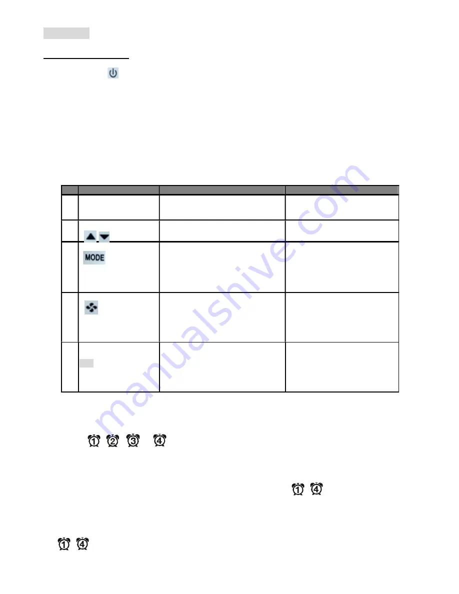
The first tier of operation includes the following settings as Figure 2. To operate:
1.
Power switch “ON” or “OFF” to start/ stop the System;
2.
After switching “ON”, press any button to start the User Mode operation.
i.
Press “MODE” button to switch over different working modes. When MODE is pressed for more than 3
seconds, the unit of temperature will toggle to change to
℉ or ℃.
ii.
Press UP/ DOWN button to increase/ decrease or rotate the values of setting.
iii.
Press “FAN” button to toggle over different fan modes.
iv.
Press “SET” button to set current time-date and timer. When SET is pressed for more than 3 seconds,
users can set the temperature schedules
.
3.
It will return to normal display with the latest setting if there’s no button pressed for 10 seconds.
#
Item
Description
Remarks
1
Normal Display
Display Current Room or Set-Point
Temperature and Current Time-Day.
Setting “-SP- “Parameter in
Engineer Table to Choose Current
Room or Set-Point Temperature.
2
Temperature Setting
View Current Set Point or Set The
Required Temperature
3
Mode Select
1. Select The Working Mode:
(1) Run/ Halt/ Stop for Schedule
2. When MODE Is Pressed For More
Than 3 Seconds, The Unit Of
Temperature Will Toggle To Change
To
℉ Or ℃.
RUN: Run Schedules.
HALT: Pause “Current” Schedule
and Use Manual SP.
STOP: Stop Using All Schedules
and Use Manual SP.
4
Fan Auto/ Continuous
1. Change Fan Mode for Auto or
Continuous Mode.
2. Auto Mode Will Stop Fan Output
During Dead Band
3. Continuous Mode Will Output Low
Speed During Dead Band
Low Speed Can Be Set Via
Engineer Table
5
Time/ Date/ Schedule
Setting
SET
1. Set Current Time in 12- Or 24- Hour
Format;
2. Set Calendar and Day of Week;
3. When SET Is Pressed for More
Than 3 Seconds, Users Can Set
Temperature Set Points Schedules
Press SET to Continue Settings.
Press MODE, FAN, Or POWER
Button to Escape Any Time During
Setting.
Special:
1. Fan bar will be shown according to the fan output from low or minimum speed to 100% of max fan output.
2. The icon
,
,
, or
will be shown on LCD while the Schedule 1,2,3, or 4 is running or being
set.
3. If press “MODE” button, there are three schedule modes “RUN, HALT, and STOP” for selection.
a.) RUN mode means activating Schedules. And at the same time an icon (
~
) will be steadily shown
on the LCD.
b.) HALT mode means temporarily pause current schedule and using manual S.P instead. And the icon
(
~
) will be flashing on the LCD.


