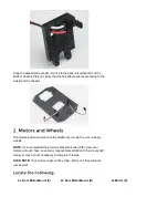


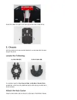
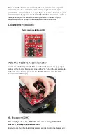
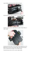
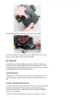

Plate assembly. Make sure the Nub Caster is on the side opposite the
motors (the bottom side).
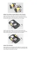
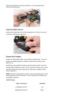
Snap the four Side Struts (E) into the diagonal slots on the four corners of
the Bottom Chassis Plate assembly.
Position the Top Chassis Plate over the Bottom Chassis Plate – but do not
snap the two plates together yet. Make sure that the front sides of each
plate line up.
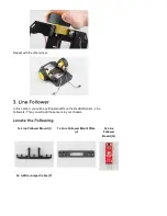
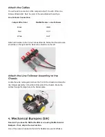
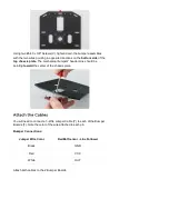
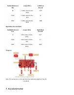
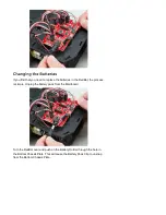
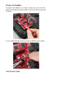
Route the wires and cables through the left and right oval slots in the Top
Chassis Plate assembly as shown. For the center line follower sensor, route
this cable through the right oval slot. Note that SIK-only cables are listed
with an asterisk (*).
NOTE:
It might be a good idea to use some pieces of masking tape to mark
which cables go to which component. It’s not necessary, but it might help
keep things organized.
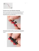
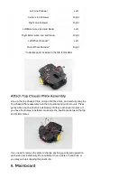
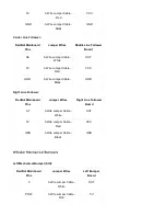
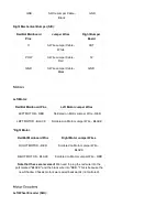
Cable Routing:
Cable Connection
Oval Side
Left Bumper Sensor*
Left
Right Bumper Sensor*
Right


