


9
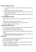
Resistance
Range
Resolution
Accuracy
200
Ω
0.1
Ω
±
0.8% of rdg
±
3 digits
2k
Ω
1
Ω
±
0.8% of rdg
±
2 digits
20k
Ω
10
Ω
±
0.8% of rdg
±
2 digits
200k
Ω
100
Ω
±
0.8% of rdg
±
2 digits
2M
Ω
1k
Ω
±
1.0% of rdg
±
2 digits
Maximum Open Circuit Voltage: 3.2V
Overload Protection: 250V dc or rms. Ac for all ranges.
Transistor hFE Test (0-1000)
Range
Test Range
Test Current
Test Voltage
NPN & PNP 0-1000
Ib=10
µ
A
Vce=3V
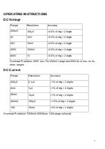
DC Voltage Measurement
1. Connect the red test lead to the
V
Ω
mA jack and black test lead to the COM
jack.
2. Set the rotary switch at desired DCV position. If the voltage to be measured
is not known beforehand, set the range switch at the highest range position
and then reduce it until satisfactory resolution is obtained.
3. Connect test leads across the source or load being measured.
4. Read the voltage value on the LCD display along with the polarity of the red
lead connection


