background image

BIOS Setup Utility

SY-6ILA

39

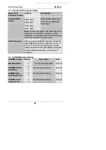
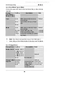
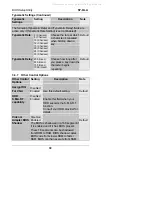
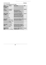
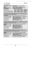
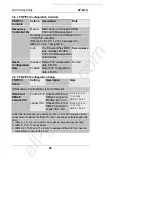
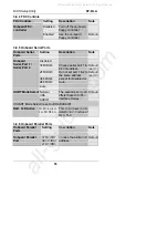
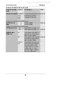
Typematic Settings (Continued)
Typematic
Settings

Setting

Description

Note

The following [Typematic Rate] and [Typematic Delay] fields are
active only if [Typematic Rate Setting] is set to [Enabled]

Typematic Rate

6 (Char/sec)
8 (Char/sec)
10 (Char/sec)
12 (Char/sec)
15 (Char/sec)
20 (Char/sec)
24 (Char/sec)
30 (Char/sec)

Choose the rate at which
a character is repeated
when holding down a
key.

Default

Typematic Delay

250 (msec)
500 (msec)
750 (msec)
1000 (msec)

Choose how long after
you press a key down the
character begins
repeating.

Default

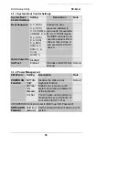
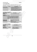
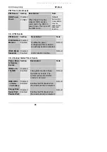
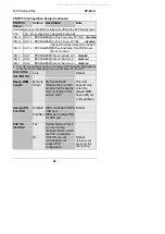
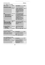
3-3.7  Other Control Options
Other Control
Options

Setting

Description

Note

Disabled

Assign IRQ
For VGA

Enabled

Use this default setting.

Default

Disabled

HDD
S.M.A.R.T.
capability

Enabled

Enable this field when your
HDD supports the S.M.A.R.T.
function.
Consult your HDD provider for
details.

Disabled
Enabled

Video or
Adapter BIOS
Shadow

The BIOS is shadowed in a 16K segment if
it is enabled and if it has BIOS present.
These 16 segments can be shadowed
from ROM to RAM. BIOS shadow copies
BIOS code from slower ROM to faster
RAM. BIOS can then execute from RAM.

Default

All manuals and user guides at all-guides.com

Summary of Contents for SY-6ILA

Page 1: ...cket 370 for Intel CeleronTM Processor Intel 440 LX AGP PCI Motherboard 66MHz Front Side Bus supported ATX Form Factor User s Guide Technical Reference All manuals and user guides at all guides com a...

Page 2: ...within it at any time without notice and without obligation to notify any person of such revision or change The information contained in this manual is provided for general use by our customers Our cu...

Page 3: ...PTER 3 BIOS SETUP UTILITY 26 3 1 SOYO COMBO SETUP 28 3 2 STANDARD CMOS SETUP 33 3 3 BIOS FEATURES SETUP 36 3 4 CHIPSET FEATURES SETUP 40 3 5 POWER MANAGEMENT SETUP 43 3 6 PNP PCI CONFIGURATION SETUP 4...

Page 4: ...DE 2 IDE 1 1 1 1 FDC ISA Slot 1 AGP Slot ATX Power Speaker Keylock Power LED Reset PWRBT Turbo LED HDD LED _ _ _ _ 1 CHAFAN JP7 JP8 1 3 Flash BIOS PC PCI SB LINK TM AUDIO PCI ES1373 LINE OUT LINE IN M...

Page 5: ...t 370 CeleronTM processor 300A 433 MHz Auto detect CPU voltage PC98 ACPI Ultra DMA 33 Supports system memory up to 384 MBytes Power on by modem or alarm Supports power on by keyboard Supports onboard...

Page 6: ...Award BIOS APM ACPI and Plug and Play function Supports multiple boot function Onboard FLASH memory for easy upgrade Y2000 Compliant Bus Controller Compliant with PCI specifications version 2 1 PCI Sl...

Page 7: ...nboard 25 pin Female Parallel Printer Port ECP EPP SPP multi mode parallel printer port COM1 COM2 2 x Onboard RS 232 Serial Ports Feature 2 x high speed UARTs with 16550 FIFO PS 2 KB 1 x Onboard PS 2...

Page 8: ...CHARGE PRECAUTIONS Make sure to ground yourself before handling the Motherboard or other system components Electrostatic discharge can easily damage the components Note that you must take special prec...

Page 9: ...a CPU support stand included in this Motherboard package 2 DIMM memory module 3 Computer case and chassis with adequate power supply unit 4 Monitor 5 PS 2 Keyboard 6 Pointing Device PS 2 mouse 7 Speak...

Page 10: ...board may be damaged by electrostatic discharge To avoid permanent damage to components ground yourself while working by using a grounding strap Otherwise ground yourself frequently by touching the un...

Page 11: ...class processor correctly Locate the CPU socket labeled Socket 370 on your Motherboard and note the distinctive pinhole arrangement Note the corresponding pinhole arrangement on the processor Socket...

Page 12: ...ing 4 Then close the socket handle to secure the CPU in place Step 2 CPU Fan Installation Your CeleronTM processor kit comes with a cooling fan Mount the fan on the processor according to the instruct...

Page 13: ...E1 IDE2 It can support up to four high speed HDD or CD ROM Connect one side of the 40 pin flat cable to the IDE device HDD or CD ROM and plug the other end to the primary IDE1 or secondary IDE2 direct...

Page 14: ...ng or disabling the keyboard Connect the KeyLock switch to the 5 pin Keylock header on the Motherboard Please install according to the following pin assignment pin 1 3 are for Power LED and pin 4 5 ar...

Page 15: ...he manufacturer has permanently set this Motherboard in Turbo mode due to most hardware and software compliance to turbo mode 5 IDE LED Attach the 2 pin IDE device LED cable to the corresponding IDE L...

Page 16: ...erboard back panel Only after you have fixed and locked the Motherboard to the computer case can you start connecting the external peripheral devices When connecting an external device use the followi...

Page 17: ...located at the rear panel of the Motherboard 4 PS 2 Mouse Similarly plug the mouse jack directly into the 6 pin female PS 2 mouse connector 5 Universal Serial Bus USB1 USB2 This Motherboard provides...

Page 18: ...card Please install according to the following pin assignment 2 Infrared IR Plug the 5 pin infrared device cable to the IR header This will enable the infrared transfer function This Motherboard meet...

Page 19: ...2 It fits in only one depending on the cable that came with your CD ROM drive Please install according to the following pin assignment 4 Other Display Cards Insert other types of VGA cards into the PC...

Page 20: ...system install according to the following pin assignment 2 Chassis Cooling Fan Some chassis also feature a cooling fan This Motherboard features a CHAFAN connector to provide 12V power to the chassis...

Page 21: ...or ISA expansion slots according to card specifications Step 11 PCI Audio Card Some PCI soundcards require a PC PCI DMA channel Attach the 5 pin cable from your PCI audio card to the SB LINK header on...

Page 22: ...d a power good signal Make sure the ATX power supply can take at least 720 mA load on the 5V Standby lead 5VSB to meet the standard ATX specification Note If you use the Wake On LAN WOL function make...

Page 23: ...make sure the ATX power supply can take at least 720mA load on the 5V Standby lead 5VSB to meet the standard ATX specification Step 14 External Suspend Button JP2 Some cases come with a suspend butto...

Page 24: ...ou must unplug the ATX power cable from the ATX power connector when performing the CMOS Clear operation Step 16 Onboard Sound Jumper JP7 The onboard audio features of your Motherboard are controlled...

Page 25: ...according to BIOS setting JP8 Setting Short pin to always enable the Power Button Open pin for a Power Button function according to the BIOS setting Step 18 Power On You have now completed the hardwa...

Page 26: ...ic checks to enter the Award BIOS Setup program The CMOS SETUP UTILITY will display on screen Follow these steps to configure the CPU settings 1 Select LOAD SETUP DEFAULT Select the LOAD SETUP DEFAULT...

Page 27: ...red to fill in the next two consecutive fields 1 the CPU Host PCI Clock and 2 the CPU Frequency CPU Frequency 300AMHz 66 x 4 5 333MHz 66 x 5 0 366MHz 66 x 5 5 400MHz 66 x 6 0 433MHz 66 x 6 5 Select th...

Page 28: ...erboard refuses to start up you can always load the default values by pressing the Ins key during boot up Step 20 Power Off There are two possible ways to turn off the system 1 Use the Shutdown comman...

Page 29: ...OS SETUP SUPERVISOR PASSWORD BIOS FEATURES SETUP USER PASSWORD CHIPSET FEATURES SETUP IDE HDD AUTO DETECTION POWER MANAGEMENT SETUP SAVE EXIT SETUP PNP PCI CONFIGURATION EXIT WITHOUT SAVING LOAD SETUP...

Page 30: ...C S T A N D A R D C M O S S E T U P B I O S F E A T U R E S S E T U P C H I P S E T F E A T U R E S S E T U P P O W E R M A N A G E M E N T S E T U P P N P P C I C O N F I G U R A T I O N L O A D S E...

Page 31: ...X 5 5 366 Mhz Current System Temp 26 C 78 F MA Wait State 2 Current CPU1 Temperature 28 C 82 F SDRAM RAS to CAS Delay 2 Current CPUFAN1 Speed 5433 RPM SDRAM RAS Precharge Time 2 Current CPUFAN2 Speed...

Page 32: ...Frequency After you have selected the host clock choose the right multiplier for the CPU Options are 2 2 5 3 3 5 4 4 5 5 5 5 6 The CPU frequency is then defined as host clock freq x multiplier and sho...

Page 33: ...SCSI device Disabled Quick Power On Self Test Enabled Provides a fast POTS at boot up Default 3 1 4 Power Management PM Events Setting Description Note BUTTON ONLY Disables the Wake Up by Keyboard fu...

Page 34: ...HotKey Ctrl F1 F12 Choose the key combination that will wake up the system Ctrl F1 to Ctrl F12 Instant off Default Soft Off by PWR BTTN Delay 4 Sec Turns off the system power 4 seconds after pushing t...

Page 35: ...t value The CPU will continue to run slow until the temperature returns back within the safe range Current CPU System Temperature C F Show the current status of CPU temperature Current CPUFAN1 CPUFAN2...

Page 36: ...44M 3 5 in Drive B None Base Memory 640K Floppy 3 Mode Support Disabled Extended Memory 31744K Other Memory 384K Video EGA VGA Halt On All But Keyboard Total Memory 32768K ESC Quit Select Item F1 Hel...

Page 37: ...nhanced IDE hard disk 528MB Mode Large Large IDE hard disk for certain hard disk Note If you have any questions on your hard disk type or mode ask your hard disk provider or previous user for details...

Page 38: ...CGA 80 Mono Monochrome 3 2 5 Halt On When the BIOS detects system errors this function will stop the system Select which type of error will cause the system halt All Errors Default No Errors All But D...

Page 39: ...N 95 Yes CC000 CFFF Shadow Disabled D0000 D3FFF Shadow Disabled Boot Up NumLock Status On D4000 D7FFF Shadow Disabled Security Option Setup D8000 DBFFF Shadow Disabled PCI VGA Palette Snoop Disabled D...

Page 40: ...he Enabled Enables the external memory Default 3 3 3 System Boot Control Settings System Boot Control Settings Setting Description Note Disabled Default Swap Floppy Drive Enabled Changes the sequence...

Page 41: ...3 5 Other Control Options Other Control Options Setting Description Note Disabled Default Enabled PCI VGA Palette Snoop The color of the monitor may be altered when using an MPEG card Enable this opti...

Page 42: ...after you press a key down the character begins repeating Default 3 3 7 Other Control Options Other Control Options Setting Description Note Disabled Assign IRQ For VGA Enabled Use this default setti...

Page 43: ...ng Enabled System BIOS Cacheable Disabled Video BIOS Cacheable Disabled Video RAM Cacheable Disabled 8 Bit I O Recovery Time 1 16 Bit I O Recovery Time 1 ESC Quit Select Item F1 Help PU PD Modify Memo...

Page 44: ...ction 60ns 50ns Choose the DRAM speed that will produce the appropriate DRAM timing for your system Default EDO RAS To CAS Delay 3 2 Use the default setting Default EDO RAS Precharge Time 3 4 Use the...

Page 45: ...ng Default Disabled Default Memory Hole At 15M 16M Enabled Some interface cards will map their ROM address to this area If this occurs select Enabled in this field Passive Release Enabled Use the defa...

Page 46: ...IDE1 Disabled MODEM Use IRQ 3 Secondary IDE 0 Disabled Secondary IDE1 Disabled Power Management User Define Floppy Disk Disabled Doze Mode Disable Serial Port Enabled Standby Mode Disable Parallel Po...

Page 47: ...ement APM you must run power exe under DOS V6 0 or later version Default PM Control by APM No V H Sync Blank Default Blank screen Video Off Method DPMS Supported Selects the method by which the monito...

Page 48: ...he set time has elapsed BIOS sends a command to the system to enter Doze Mode System clock drops to 33MHz The following Standby Mode field may be configured only if Power Management is set to User Def...

Page 49: ...when a no activity event is detected Default Disabled Default IRQ 8 Break Suspend Enabled Alarm function is active 3 5 4 Reload Global Timer Events Power Down Resume Events Setting Description Note Di...

Page 50: ...n IRQ For USB Enabled IRQ 11 assigned to PCI ISA PnP IRQ 12 assigned to PCI ISA PnP PNP OS Installed No IRQ 14 assigned to PCI ISA PnP IRQ 15 assigned to PCI ISA PnP DMA 0 assigned to PCI ISA PnP DMA...

Page 51: ...PCI Configuration Setup PNP PCI Setup Setting Description Note If Resources Controlled By is set to Manual PCI ISA PnP Choose IRQ and DMA assigned to PCI ISA PnP card IRQ 3 4 5 7 9 10 11 12 14 15 DMA...

Page 52: ...RQ 3 PCI ISA PnP Onboard Serial port 2 disabled 4 Your OS may reassign another interrupt to a PCI slot after BIOS passes control to the OS especially if you use Windows 95 98 or NT Auto Default Slot 1...

Page 53: ...to any problem after changing the BIOS configuration please load the SETUP DEFAULTS for stable performance ROM PCI ISA BIOS CMOS SETUP UTILITY AWARD SOFTWARE INC SOYO COMBO SETUP STANDARD CMOS SETUP B...

Page 54: ...mal IDE Secondary Master PIO Auto IDE Secondary Slave PIO Auto IDE Primary Master UDMA Auto Onboard Parallel Port 378 IRQ7 IDE Primary Slave UDMA Auto Parallel Port Mode SPP IDE Secondary Master UNMA...

Page 55: ...ntrol timing Default Disabled IDE Primary Master UDMA Primary Slave UDMA Secondary Master UDMA Secondary Slave UDMA Auto Select Auto to enable Ultra DMA Mode support Default Disabled Turn off the on b...

Page 56: ...2 Auto Choose serial port 1 2 s I O address Do not set port 1 2 to the same address except for Disabled or Auto Normal Default IrDA UART Mode Select ASKIR The second serial port offers these InfraRed...

Page 57: ...lel Port Mode is set to EPP mode EPP 1 9 Select EPP port type 1 9 EPP Mode Select EPP 1 7 Select EPP port type 1 7 Default On The system will switch on when power comes back after a power failure Off...

Page 58: ...ed on the setting you have made in the Security Option of the BIOS FEATURES SETUP section the password prevents access to the system or the setup program by unauthorized users Follow this procedure to...

Page 59: ...information is lost and you must run the BIOS setup program again Note If you do not wish to use the password function press Enter directly and the following message appears 3 Enter your new password...

Page 60: ...PSET FEATURES SETUP POWER MANAGEMENT SETUP PNP PCI CONFIGURATION LOAD SETUP DEFAULTS LOAD BIOS DEFAULTS INTEGRATED PERIPHERALS SUPERVISOR PASSWORD USER PASSWORD IDE HDD AUTO DETECTION SAVE EXIT SETUP...

Page 61: ...YLS HEAD PRECOMP LANDZ SECTOR MODE Primary Master Select Primary Master Option N Skip N OPTIONS SIZE CYLS HEAD PRECOMP LANDZ SECTOR MODE 2 Y 1707 827 64 0 3308 63 LBA 1 1707 3309 16 65535 3308 63 NORM...

Page 62: ...ine in and mic jack convenient to directly plug in all your external audio devices Your SY 6ILA Motherboard is making use of the CREATIVE ES1373 sound chipset technology and applications programs Note...

Page 63: ...on your SY 6ILA Motherboard Note This Motherboard requires a speaker with built in amplifier Amplified Speaker to generate proper output sound volume MIC JACK LINE IN LINE OUT Amplified Speakers MIC...

Page 64: ...vailable for installation and a database in HTML format with information on SOYO Motherboards and other products The SOYO CD Start Up Program automatically detects which SOYO Motherboard you own and d...

Page 65: ...vers software that can be installed with your Motherboard The Start Up program displays the drivers available for the particular model of Motherboard you own We recommend that you only install those d...

Page 66: ...eedPro Busmaster Driver for Win 95 98 Without the busmaster drivers the CPU will need to be involved every time data is read from or written to the Harddisk The busmaster drivers make use of DMA Direc...

Page 67: ...ature Fan speed and Voltages can be monitored It is also possible to set alarms when current system values exceed or fall below pre set values Creative Ensoniq Sound Drivers These drivers have to be i...

Page 68: ...r your convenience this information is available in HTML format similar to the format widely used on the Internet SOYO CD HTML Database in English The list of menu options may vary between languages N...

Page 69: ...driver installation and return to the main menu Notice 2 Once you have selected a driver the system will automatically exit the SOYO CD to begin the driver installation program When the installation i...

Page 70: ...r audio card is working properly 1 Click the Start button point to Programs point to Accessories point to Multimedia for Windows 98 choose Entertainment and then click Media Player 2 On the Device men...

Page 71: ...s on the screen to complete the installation Uninstalling Software in Windows 95 98 1 Click the Start men point to Settings and click Control Panel 2 Double click the Add Remove Programs icon 3 On the...

Page 72: ...llation CD into your CD ROM drive The AutoPlay screen appears 2 Follow the instructions on the screen to complete the installation Testing the Installation in Windows NT 4 0 You may run a simple appli...

Page 73: ...perties windows and restart your computer Reinstalling the Audio Drivers From the Installation Disc You may want to reinstall the audio drivers if you think they are corrupted To do so 1 Insert the in...

Reviews: