background image

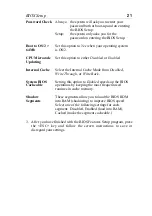
BIOS Setup

29

Allocate IRQ to
PCI VGA

Choose either 

Disabled

 or 

Enabled

 depending on

whether or not your VGA card requires an IRQ.

DMA Channel
List

Each option on this list can be set to either 

PnP

 or

ISA/EISA

.  Default is 

PnP

.  If you have an ISA

card that requires a DMA channel, set it to

ISA/EISA

 here.

IRQ List

Each option on this list can be set to either

PCI/PnP

 or 

ISA/EISA

.  Default is 

PnP

.  If you

have an ISA card that requires an IRQ, set it to

ISA/EISA

 here.

Reserved
Memory Size

Choose from the following settings: 16k, 32k,
64k, or Disabled.

Reserved
Memory Address

Set the address through this option.

3. After you have finished with the PCI Slot Configuration, press the

<ESC> key and follow the screen instructions to save or disregard
your settings.

Load BIOS Defaults & Load Setup Defaults

These two items both set the BIOS settings back to their default values.
The difference between the two is that 

BIOS Defaults

 loads the most

conservative values, meaning that it is best to load the BIOS defaults
whenever you are experiencing problems; on the other hand, 

Setup

Defaults

 setting are optimized for speed and are usually the best settings

to load.

Default settings can be loaded through choosing one of two items after
which a message appears:

ÒLoad SETUP Defaults (Y/N)? NÓ

OR

ÒLoad BIOS Defaults (Y/N)?NÓ

Pressing <Enter> key will not load the defaults, you need to press Y and
then <Enter> key to load the default values.

Summary of Contents for 6KD

Page 1: ...6KD 82440 LX PCI Mainboard User s Guide Technical Reference...

Page 2: ...evise the manual or make changes in the specifications of the product described within it at any time without notice and without obligation to notify any person of such revision or change The informat...

Page 3: ...Connector 8 RST Hardware Reset Control 8 IDE1 IDE2 On board Primary Secondary IDE HDD Connectors 8 COM1 COM2 Connectors 8 IDE LED IDE HDD LED Connectors 9 FDC Connector 9 PRT Parallel Port Connector 9...

Page 4: ...Hardware Monitor 32 Supervisor Password 33 IDE HDD Auto Detection 34 Quick Installation Guide 35 Motherboard Layout 35 Memory Configurations 35 Connectors and Jumper Settings 36 Default I O Settings...

Page 5: ...ction of memory type supports ECC or Parity configuration has onboard memory configurations from 8MB to 512MB BUS controller complies with the PCI specifications v2 1 five 32 bit PCI slots Masters and...

Page 6: ...s damage to the board contact your dealer immediately Electrostatic Discharge Precautions Make sure you ground yourself before handling the mainboard or other system components Electrostatic discharge...

Page 7: ...1 for PII CPU 9 IDE1 IDE2 Connector 2 82440LX Chipset 10 Floppy Connector 3 Ultra I O Chip 11 COM1 COM2 Connector 4 PnP FLASH BIOS 12 Parallel Port Connector 5 ISA Slot 13 PS 2 Keyboard Connector 6 PC...

Page 8: ...443LX 3V Lithium Battery PRT DIMM 4 DIMM 3 DIMM 2 DIMM 1 JP5 1 RST PWRBT Keylock SPK IDE LED TB LED PW LED Slot 1 for Pentium II CPU 5 JP14 1 1 2 5 6 JP15 1 6 5 10 1 JP43 1 JP42 Figure 1 2 Mainboard D...

Page 9: ...a default 1 Clear CMOS data 1 CPU Type Configuration This mainboard is designed so that it is not necessary to use any jumpers to set the CPU frequency and multipliers onboard Instead of using jumpers...

Page 10: ...n 3 3V EDO SDRM Unbuffered DIMM The mainboard supports from 8 to 512 Mbytes with no other restrictions on memory configurations You can install DRAM in any combination without having to rely on a memo...

Page 11: ...n male header connector Plug the connector from the power directly onto the board connector while making sure the pin1 is in its position 3 3V 3 3V GND 5V GND 5V GND PW 0K 5VSB 12V 3 3V 12V GND PS ON...

Page 12: ...a lock that may be installed on the system case for enabling or disabling the keyboard This connector also attaches to the case s Power LED Pin 1 3 for power LED pin 4 5 for keylock SPK Speaker Connec...

Page 13: ...onnector Momentary Type Attach a two pin switch to this connector for turning the ATX power supply on off JP42 JP43 CPU Cooling Fan Connector This 3 pins connector provides 12V power for the CPU cooli...

Page 14: ...card JP44 Pin Assignment 5V GND SENSOR 1 2 3 JP15 PCI Audio Card Connector This 6 pin connector is used for plugging the PCI Audio card s PCI request grant sideband signals connector into Through thi...

Page 15: ...CPU on to your motherboard These steps are the same for both Slot 1 CPUs Step 1 Find the ATX PW and the Slot 1 on the board and set the board in the direction as follows before doing any installation...

Page 16: ...12 Hardware Setup Step 2 Insert the supporting base which is shown below into the two holes directly to the left of the 2 sets of screws that have just been inserted on to the board Slot 1 ATX PW...

Page 17: ...Hardware Setup 13 Step 3 Insert the 2 latches into the two holes of the supporting base and then turn them 90 to secure the CPU ATX PW...

Page 18: ...14 Hardware Setup Step 4 Set the retention clip right on the top of the 2 sets of screws which are along the sides of Slot1 and then tighten the 4 screws on the retention clip Slot 1 ATX PW...

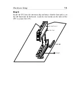
Page 19: ...5 Insert the CPU into the retention clip and notice that the heat sink is on the left hand side of the board Lock the two latches on the sides of the CPU to secure the CPU Slot 1 Non boxed Pentium II...

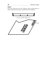
Page 20: ...16 Hardware Setup Step 6 Insert the clip portion of the CPU supporter which is shown below so that the heat sink can sit on the top of the whole CPU supporter Top View of CPU Support Clip ATX PW...

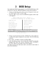
Page 21: ...RATION LOAD SETUP DEFAULTS LOAD BIOS DEFAULTS INTEGRATED PERIPHERALS HARDWARE MONITOR SETUP SUPERVISOR PASSWORD USER PASSWORD IDE HDD AUTO DETECTION SAVE EXIT SETUP EXIT WITHOUT SAVING Esc Quit Select...

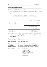
Page 22: ...Not Installed Month Jan Dec ESc Exit Day 01 31 Select Item Year 1901 2099 PU PD Modify Shift F2 Color Base Memory 640Kb Other Memory 384Kb Extended Memory 31Mb 32Mb 2 Use arrow keys to move between i...

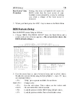
Page 23: ...adow Disabled D800 16K Shadow Disabled DC00 16K Shadow Disabled Quick Boot Disabled 1st Boot Device Floppy 2nd Boot Device IDE 0 3rd Boot Device CDROM Try other Boot Devices Yes Initial Display Mode B...

Page 24: ...tion to either Silent or BIOS Floppy Access Control Set this option to enable to write to floppy disks Choices are either Read Write or Read Only Hard Disk Access Control Set this option to enable to...

Page 25: ...Internal Cache Mode from Disabled Write Through or Write Back System BIOS Cacheable Setting this option to Enabled speeds up the BIOS operations by keeping the most frequent used routines in cache mem...

Page 26: ...gacy support Disabled Auto Configure EDO DRAM Tim Enabled EDO DRAM Speed ns 60 EDO Read Burst Timing x222 EDO Write Burst Timing x222 EDO RAS Precharge Timing 3 Clocks EDO RAS to CAS Delay 3 Clocks MA...

Page 27: ...rity memory necessary ECC Checks for and corrects errors ECC memory necessary VGA Frame Buffer USWC PCI Frame Buffer USWC Set these options to either Enabled or Disabled Fixed Memory Hole Set this opt...

Page 28: ...tem at a busclock of 75Mhz to avoid problems Disabled Your system will run on the INTEL specified busclock of 66Mhz CPU Frequency Select the frequency of your Pentium II CPU from the following 233 266...

Page 29: ...E IRQ N A Display Activity Ignore Device 6 Serial port 1 Monitor Device 7 Serial port 2 Monitor Device 8 Parallel port Ignore Device 5 Floppy Disk Monitor Device 0 Primary Master ID Monitor Device 1 P...

Page 30: ...ose either Monitor or Ignore for all these devices Monitor Makes the BIOS check for activity on these devices resetting the standby and suspend timers if activity is detected System Thermal Choose Ign...

Page 31: ...up when the modem detects an incoming call RTC Alarm Resume from Soft Off Set this option to Enabled will enable the system to wake up at a predetermined time as set by the next four items The system...

Page 32: ...Channel 0 PnP DMA Channel 1 PnP DMA Channel 3 PnP DMA Channel 5 PnP DMA Channel 6 PnP DMA Channel 7 PnP IRQ3 PCI PnP IRQ4 PCI PnP IRQ5 PCI PnP IRQ7 PCI PnP IRQ9 PCI PnP IRQ10 PCI PnP IRQ11 PCI PnP IR...

Page 33: ...After you have finished with the PCI Slot Configuration press the ESC key and follow the screen instructions to save or disregard your settings Load BIOS Defaults Load Setup Defaults These two items...

Page 34: ...lues Shift F2 Color F6 Load BIOS Defaults F7 Load Setup Defaults OnBoard FDC Auto OnBoard Serial PortA Auto OnBoard Serial PortB Auto Serial PortB Mode N A IR Duplex Mode N A IrDA Protocol N A IR Port...

Page 35: ...onboard floppy controller The serial port address options are the same as those for serial port A however do not select the same address for both serial port A and B IR Port Support Select either Ena...

Page 36: ...B Wake Up Function Set this option to Enabled to enable the Keyboard Wake Up function Mouse Wake up Function Set this option to Enabled to enable the Mouse Wake Up function Onboard IDE Set this option...

Page 37: ...d first in order to proceed The following message appears Enter Password 2 Enter a password and press Enter If you do not wish to use the password function you can just press Enter and a Password disa...

Page 38: ...all the IDE compatible devices such as Harddisks and CD ROM drives which are connected to the system The correct settings will automatically be stored into Standard CMOS Setup and after finishing the...

Page 39: ...2 KB Conn ATX PW FDC IR FLASH BIOS 4 PS 2 Mouse Conn PCI SLOT 83977FX ISA SLOT AGP Port Slot 1 for Pentium II CPU 82443LX 3V Lithium Battery PRT DIMM 4 DIMM 3 DIMM 2 DIMM 1 JP5 1 RST PWRBT Keylock SP...

Page 40: ...ower Supply On Off Switch PWRBT of speakers to lock switch to this Connect your power switch to this jumper momentary switct type this jumper jumper IrDA Infrared Devices Connector IR pin 6 10 reserve...

Reviews: