background image

EZ C

OM 

C

OMBINATION 

O

VEN

P

ARTS

O

PERATOR

M

ANUAL 

1182851 

REV 

2

P

AGE 

37

PARTS

6 POSITION TERMINAL STRIP

(PART OF WIRING HARNESS, 1182398)

2 POSITION TERMINAL STRIP

(PART OF WIRING HARNESS, 1182398)

1

2

3

4

5

6

7

8

9

10

11

12

13

14

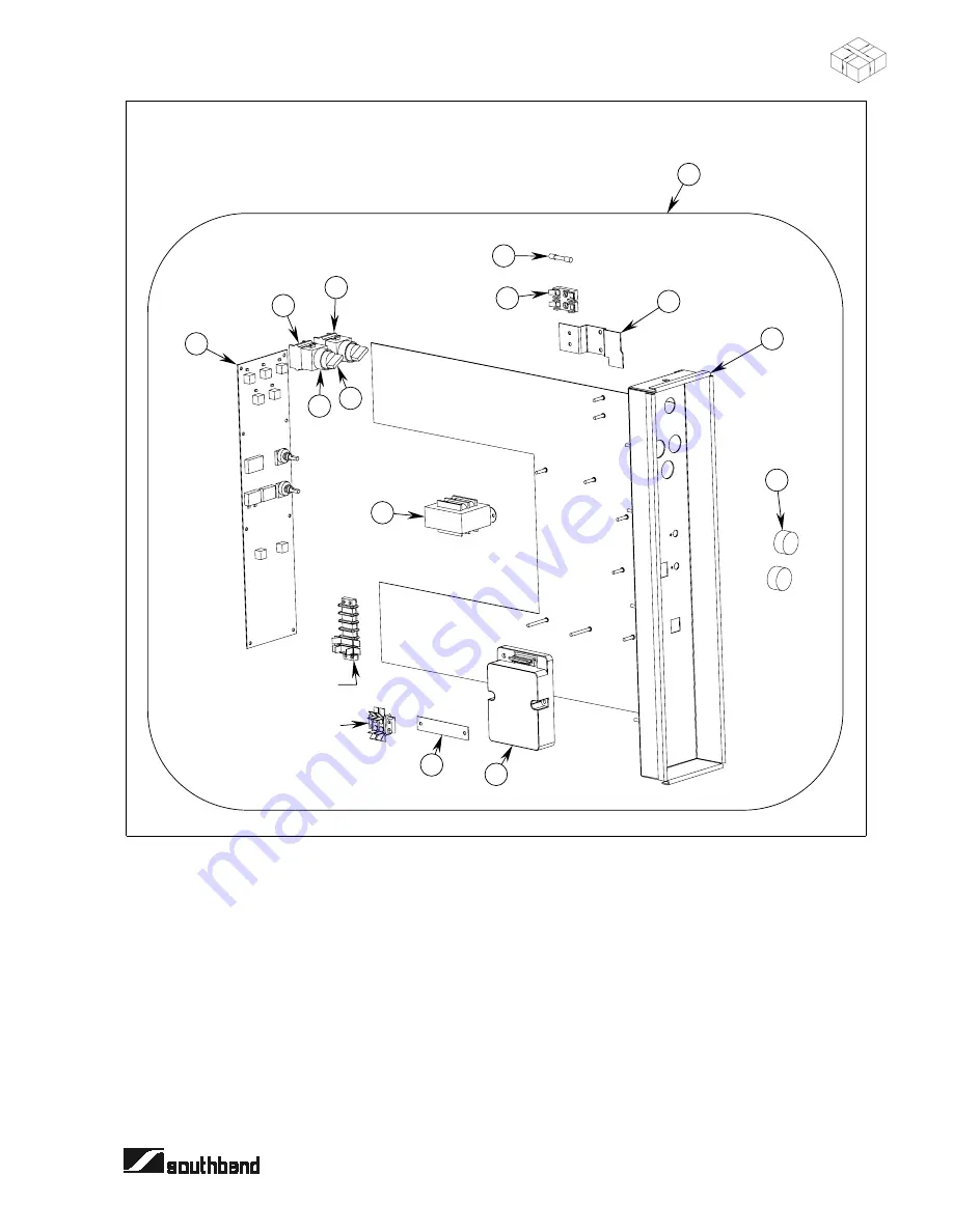
Control Panel Subassembly Parts

See parts list on previous page.

Summary of Contents for EzCom CG/12SC

Page 1: ...mage injury or death Read the installation operating and maintenance instructions thoroughly before installing or servicing this equipment 1100 Old Honeycutt Road Fuquay Varina NC 27526 www southbendn...

Page 2: ...WARNING FIRE HAZARD FOR YOUR SAFETY Do not store or use gasoline or other flammable vapors and liquids in the vicinity of this or any other appliance Keep area around appliances free and clear of com...

Page 3: ...12SC and CG 22SC The serial plate is located behind the lower front panel on the left side On double stacked models each oven has its own serial plate Table of Contents Specifications 4 Installation...

Page 4: ...he entire time the EZ Com is turned on and the flame is proven by a flame sensor WATER Cold water consumption is regulated to approximately 0 5 gallons per minute per oven Water pressure must be in th...

Page 5: ...71 33 4 848 29 8 757 26 5 673 29 2 742 18 3 465 20 2 513 2 0 51 12 5 319 17 6 447 Cavity Drain Front Trough Drain Gas Connection Water Inlet Power Cord FRONT RIGHT SIDE TOP BACK 40 7 1034 38 5 978 23...

Page 6: ...57 13 5 342 9 9 251 6 6 168 9 3 235 18 3 465 20 2 513 2 0 51 12 5 319 17 6 447 Cavity Drain Front Trough Drain Gas Connection Water Inlet Power Cord The upper oven has separate utility connections eac...

Page 7: ...INSPECT FOR SHIPPING DAMAGE All containers should be examined for damage before and during unloading The freight carrier has assumed responsibility for its safe transit and delivery If damaged equipm...

Page 8: ...o support the load 2 Screw the four casters into the threaded holes in the bottom corners of the EZ Com The two casters with a locking brake should be attached to the front corners 3 Gently lower the...

Page 9: ...be on the side of the hanger closest to the edge of the oven LEGS NOT SHOWN Install legs first Side View Bottom View A A A 3 Attach the pan stop to the shelf by first inserting the tab on the bottom o...

Page 10: ...slide the guide toward the center of the oven until the hooks drop through the final position holes in the frame hangers LEGS NOT SHOWN Install legs first Side View Showing Guide in Final Position Fi...

Page 11: ...r enters through this area Be sure to inspect and clean the ventilation system according to the ventilation equipment manufacturer s instructions NOTICE Proper ventilation is the owner s responsibilit...

Page 12: ...e Oven Cavity Drain 2 O D tube Front Trough Drain 3 4 O D tube Electrical Connection 120 volt ovens have a 6 foot power cord with a 120VAC grounded plug 208 volt ovens have a hole for a strain relief...

Page 13: ...of local codes with the National Electrical Code ANSI NFPA 70 or the Canadian Electric Code CSA C22 2 as applicable WARNING A POSITIVE GROUND CONNECTION IS ESSENTIAL DO NOT ALLOW ANY TAMPERING OR ADJU...

Page 14: ...rt as possible There should be no horizontal piping between the oven and the air gap over the open funnel The open funnel is intended to eliminate any water from entering the oven because of a blocked...

Page 15: ...sized or low pressure lines will restrict the volume of gas required for satisfactory performance Fluctuations of more than 25 on natural gas or 10 on propane gas will create problems and affect burne...

Page 16: ...door s for proper alignment tension seal and adjustment 6 Check timers switches and motor for proper installation and operation 7 Check for any damage to unit from shipping or installation 8 Check for...

Page 17: ...he setpoint temperature the light above the button will flash until the setpoint temperature is reached In Steam Mode the setpoint temperature is preset to 215 F to allow pure slightly superheated ste...

Page 18: ...ected to maintain a high humidity cooking environment STEAM INJECT mode injects steam for as long as the button is held This button can only be used when in OVEN mode COOL DOWN mode combines high fan...

Page 19: ...325 F 165 C 30 min 2 pan uncovered Chocolate brownies Oven 325 F 165 C 25 min Sheet pans Coffee cake apple Oven 300 F 150 C 25 min Coffee cake sour cream Oven 300 F 150 C 25 min Also try in Combi mode...

Page 20: ...amburgers Frozen patties Combi 400 F 205 C 10 min Perforated sheet pan Herbed pot roast Combi 250 F 120 C 3 hours 2 solid pan Hot dogs Steam N A 7 min 2 perforated London broil Combi 500 F 260 C 15 mi...

Page 21: ...n Single layer BBQ boneless rib for sandwich retherm Combi 250 F 120 C 15 min Sheet pan BBQ pork for sandwich Boston butts raw Combi 250 F 120 C 2 hours Sheet pan with sauce Bratwurst Steam N A 10 min...

Page 22: ...eet pan Turkey breast Combi 325 F 165 C 1 hour Sheet pan Vegetables Menu Item Mode Temperature Cooking Time Proper Pan Tips Asparagus Steam N A 8 min 2 perforated Asparagus egg au gratin Steam N A 14...

Page 23: ...min 2 solid pan Sprinkle w lemon white wine Peas and mushroom frozen Steam N A 14 min 2 perforated Separate ice encased vegetables Peas garden frozen Steam N A 7 min 2 perforated Ratatouille Combi 300...

Page 24: ...TROLS This could result in expensive repairs and or electrical shock De energize all power to equipment before cleaning the equipment NOTICE VENT SYSTEM At least twice a year the unit s venting system...

Page 25: ...r as gently as possible in the direction of the polished lines will not mar the finish of the stainless steel NEVER RUB WITH A CIRCULAR MOTION Soil and burnt deposits which do not respond to the above...

Page 26: ...lubrication when required CONTROL PANEL ERROR CODES The Southbend EZ Com is equipped with a printed circuit board controller that undergoes a diagnostic check every time the EZ Com is turned on This d...

Page 27: ...elow that corresponds to the malfunction then turn to the corresponding page Follow the flowchart on that page until the problem is solved Symptom Page Unit Not Working No Lights 28 Unit Not Heating P...

Page 28: ...serial plate Is voltage the rated voltage of oven With switch in ON position check voltage between TB B1 and TB B2 Is voltage the rated voltage of oven Test and replace power switch as necessary Chec...

Page 29: ...burners come on Go to page 32 Blower Not Running Properly Does blower come on Yes Yes Place unit in oven mode at 200 F Open door Depress door switch Check gas manifold pressure There is a tap on the...

Page 30: ...Test and replace bad ignitor as required Check manifold pressure during first 30 seconds of operation There is a tap on the gas combination valve for this purpose Make sure that flame sensors are posi...

Page 31: ...r from unit if desired Is resistance between 1 and 10 megaohms Replace solenoid valve Turn off water supply to unit Remove water supply copper tube from compression fitting at inlet to solenoid valve...

Page 32: ...pin connector Place fan switch in HI position Locate the terminals where Wires 21 and 55 are attached and check for continuity between these terminals Place the fan switch in LO position Locate the t...

Page 33: ...EZ COM COMBINATION OVEN TROUBLESHOOTING OPERATOR S MANUAL 1182851 REV 2 PAGE 33 Wiring Diagram for 120 Volt Ovens...

Page 34: ...TROUBLESHOOTING EZ COM COMBINATION OVEN PAGE 34 OPERATOR S MANUAL 1182851 REV 2 Wiring Diagram for 208 Volt Ovens...

Page 35: ...ng parts please supply the Model Number Serial Number Part Number Description Finish and Electrical Characteristics as applicable For parts not listed consult a Southbend Authorized Parts Distributor...

Page 36: ...use time delay 10 A for 208V ovens only 8 1178391 Fuseblock controls 9 1178534 1 Bracket on off switch 10 1180931 1 Panel weld assembly control 11 1172275 2 Plastic knob 12 1180635 1 Ignition module 1...

Page 37: ...NUAL 1182851 REV 2 PAGE 37 PARTS 6 POSITION TERMINAL STRIP PART OF WIRING HARNESS 1182398 2 POSITION TERMINAL STRIP PART OF WIRING HARNESS 1182398 1 2 3 4 5 6 7 8 9 10 11 12 13 14 Control Panel Subass...

Page 38: ...1 1180953 1 Hanger hose 12 1182169 1 Spray nozzle bracket 13 1177523 1 Bracket rear gas pipe 14 1180660 2 Bracket front and rear pipe support 15 1180655 1 Base weld assembly 16 1180935 2 Frame horizon...

Page 39: ...OMBINATION OVEN PARTS OPERATOR S MANUAL 1182851 REV 2 PAGE 39 PARTS 1 2 3 4 5 6 7 8 9 10 11 12 13 15 16 17 18 19 20 21 22 16 23 24 26 27 28 20 14 18 25 Frame and Exterior Parts See parts list on previ...

Page 40: ...h MPT x 3 16 inch tube 6 1182695 2 Thermostat probe assembly 7 1180671 1 Flue duct weld assembly 8 1180992 1 Insul cover for flue 9 1180996 1 Spring relief valve 10 1180997 1 Disk pressure relief 11 1...

Page 41: ...scription 1 1180618 1 Door subassembly assembled 2 1182535 1 Panel door weld assembly 3 1180691 1 Insulation door 4 1146303 8 Screw 8 x 1 2 5 1180977 4 Hinge door 6 1180627 1 Gasket door 7 1180685 1 P...

Page 42: ...e nat 43 drill 1036610 4 Orifice spud propane 54 Drill option 17 1036605 4 Air collar PLTD 18 1036607 4 Burner 4 inch 19 1099114 1 Nut male 20 1182531 1 Tube main pilot up 21 1061298 1 Union brass 22...

Page 43: ...ARTS OPERATOR S MANUAL 1182851 REV 2 PAGE 43 PARTS 1 2 3 4 5 6 7 8 9 10 11 8 12 13 14 15 16 17 18 19 20 21 22 23 24 25 26 27 28 29 30 31 32 33 34 35 37 38 39 8 39 36 Burner and Gas Train Parts See par...

Page 44: ...onents see page 45 1182697 1 Adapter GH male to 3 8 female NPT 2 1182694 1 Spray hose 3 1180959 1 Spray nozzle 3 4 FGH 4 1180944 1 Tube spray supply 5 P5552 1 Connector 1 4 6 1174620 1 Spray nozzle 7...

Page 45: ...let subassembly assembled 2 1180956 1 Tee 3 8 brass 3 1178283 1 Bushing brass 1 4 inch x 3 8 inch 4 1173433 2 Nipple 1 4 NPT 5 1173428 1 Strainer Y in line 6 1180669 1 Bracket water inlet 7 1180937 1...

Page 46: ...iption 1 1180633 1 Fan water dispersing 2 1180934 1 Blower wheel weld assembly 3 1180903 1 Fitting motor shaft seal 4 1180909 1 Washer wave spring ss 5 1180910 1 Washer flat 6 1180932 1 Packing materi...

Page 47: ...47 PARTS Legs and Caster Parts 1 2 Key Part Number Qty Description 1 1174265 1 Caster package 4 bolt 2 1184005 1 Leg assembly caster 1146213 20 Bolt 3 8 16x1 hex head 1146505 20 Washer 5 16 flat 1146...

Page 48: ...oling pan kit shallow depth 1184044 1 Cooling pan kit bakery depth 1 1184022 2 Rack hanger G E ser co 2 1184025 1 Stop channel 3 6660 8 Clip side rack support 4 1175438 2 Rack guide 11 pos shallow 117...

Page 49: ...EZ COM COMBINATION OVEN OPERATOR S MANUAL 1182851 REV 2 PAGE 49 Notes...

Page 50: ...EZ COM COMBINATION OVEN PAGE 50 OPERATOR S MANUAL 1182851 REV 2 Notes...

Page 51: ...EZ COM COMBINATION OVEN OPERATOR S MANUAL 1182851 REV 2 PAGE 51 Notes...

Page 52: ...cognize however that replacement parts and occasional professional service may be necessary to extend the useful life of this unit When service is needed contact a Southbend Authorized Service Agency...

Reviews: