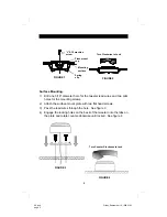
background image

Flush Mounting: 

1) Cut a 2 1/16” (52mm) diameter hole through the 

mounting surface.  If the surface is covered with 
cloth or carpet, be careful not to tear or pull the 
material.  Sometimes it is a good idea to peel the 
material away, and then trim it by hand. 

2) Secure the cup in the mounting cutout by using 

the spring clips and screw provided.  Slip the 
spring clips through the bottom of the cup and 
tighten the screw until the cup is firmly seated.  
See Figure 1. 

3) Once the cup is secure, mount the tweeter into 

the cup making sure to first pass the tweeter 
wires through the openings in the cup.  Turn the 
outer swivel ring, (not the tweeter) clockwise  to 
lock it into place.  See Figure 2.  The tweeter 
may be tilted approximately 15 degrees to 
optimize dispersion and imaging. 

INSTALLING 

THE   

TWEETER 

The first step in a successful installation is thorough 
planning.  Choose the location for your speaker 
components carefully.  Follow these suggestions to 
ensure proper imaging and the best performance: 

Select a location where each tweeter and 
midrange/woofer can be mounted close to each 
other.  A good rule of thumb is a maximum of 
one foot from cone to tweeter. 

Choose a location that offers the least 
obstruction of sound to your ears. 

Try to mount the components on the same plane. 

Always check behind the chosen mounting 
locations to make sure that there are no 
obstructions (e.g., trunk springs, gas tank, 
window tracks) or wires in the way, as well as to 
make sure that there is ample support on which 
to mount the components.   

LOCATION 

AND  

MOUNTING 

60.pub 
page 4

Friday, September 10, 1999 21:03 

Summary of Contents for SPL 60

Page 1: ...1 2 Ohm Nominal Component Speaker System OWNER S MANUAL 60 pub page 1 Friday September 10 1999 21 03 ...

Page 2: ...________________________________ Date of Purchase ___________________________________________ Date of Installation _________________________________________ Dealer s Name ____________________________________________ Before beginning your installation please check to see that the number of parts contained in your box match the list below Hardware 4 each Stainless steel tweeter spring clips for SPL ...

Page 3: ...ing SPL 6X Passive Crossover Network The SPL 6X crossover consists of high quality multi element components with a two position tweeter level control This allows tailoring high frequency output to the installation and individual preferences 24 dB octave Acoustic Summation Crossover Slopes Variable tweeter control for added flexibility Dynamic tweeter protection allows for improved power handling a...

Page 4: ...er may be tilted approximately 15 degrees to optimize dispersion and imaging INSTALLING THE TWEETER The first step in a successful installation is thorough planning Choose the location for your speaker components carefully Follow these suggestions to ensure proper imaging and the best performance Select a location where each tweeter and midrange woofer can be mounted close to each other A good rul...

Page 5: ...or the mounting screws 2 Attach the surface mount plate with two flat head screws 3 Pass the lead wires through the hole See figure 3 4 Engage the locking holes on the back of the tweeter onto the tabs on the plate and rotate counter clockwise until locked See figure 4 FIGURE 3 FIGURE 4 Turn Counter Clockwise to Lock Turn Clockwise to Lock 60 pub page 5 Friday September 10 1999 21 03 ...

Page 6: ...rely mounted to prevent unwanted vibration 1 Mark the speaker location by using the template provided 2 Cut the opening and debur the edges with a file 3 Hold the speaker in place against the mounting surface and mark the mounting bolt holes 6 Drill the appropriate size hole for the screws provided 7 Place the SPL 6 into the trim ring make the speaker wire connections then install the speaker trim...

Page 7: ...m illustrating the wiring of the SPL 60 Component Speaker System It is important to make sure that all connections are in phase that is positive is connected to positive and negative is connected to negative since an out of phase connection will cause a dislocated image and low bass output We suggest using premium cable The connectors provided with this system will accommodate wire from 12 gauge t...

Page 8: ...8 H x 4 3 4 D SPL 6 Midrange Woofer Frequency Response 55 Hz 3200 Hz 3dB Continuous Power Handling 50 watts with SPL 6X Crossover Peak Program Power Handling 100 watts with SPL 6X Crossover Sensitivity 94 dB SPL at 1 meter 2 83 Volts Nominal Impedance 2Ω Nominal Driver Diameter 6 1 2 Mounting Cut Out Diameter 5 5 8 Mounting Depth 2 3 4 Frequency Response 3200 Hz 20 000 Hz 3dB Sensitivity 94 dB SPL...

Reviews: