background image

SOUNDMAX

SM-SA6021

2

YOUR NEW HIGH FIDELITY BRIDGEABLE/STEREO AMPLIFIER IS DESIGNED TO DELIVER MAXIMUM ENJOYMENT
AND ONE YEAR OF TROUBLE FREE SERVICE.

         Table of contents

TABLE OF CONTENTS ................................................................................................................................................. 2

 FEATURES.................................................................................................................................................................... 3

PRECAUTIONS:............................................................................................................................................................. 3

INSTALLATION.............................................................................................................................................................. 5

CONNECTIONS ............................................................................................................................................................. 6

OPERATION ELEMENTS AND IN / OUTPUTS............................................................................................................. 7

FIG. 2 POWER SUPPLY/REMOTE TURN-ON CONNECTION ..................................................................................... 8

FIG. 3 STEREO MODE................................................................................................................................................... 9

FIG. 4 BRIDGE MODE WITH STEREO CAR RADIO .................................................................................................. 10

FIG. 5  DUAL MODE SYSTEM..................................................................................................................................... 11

FIG. 6 OPERATING ELEMENTS AND IN/OUTPUTS.................................................................................................. 12

TROUBLE SHOOTING GUIDE .................................................................................................................................... 13

SPECIFICATION .......................................................................................................................................................... 14

Summary of Contents for SM-SA6021

Page 1: ...SM SA6021 2 CHANNEL CAR AMPLIFIER 2 Instruction manual ...

Page 2: ... Table of contents TABLE OF CONTENTS 2 FEATURES 3 PRECAUTIONS 3 INSTALLATION 5 CONNECTIONS 6 OPERATION ELEMENTS AND IN OUTPUTS 7 FIG 2 POWER SUPPLY REMOTE TURN ON CONNECTION 8 FIG 3 STEREO MODE 9 FIG 4 BRIDGE MODE WITH STEREO CAR RADIO 10 FIG 5 DUAL MODE SYSTEM 11 FIG 6 OPERATING ELEMENTS AND IN OUTPUTS 12 TROUBLE SHOOTING GUIDE 13 SPECIFICATION 14 ...

Page 3: ...ttery terminal must be disconnected before any electrical connections are made Be sure choosing a location that provides substantial ventilation for the amplifier The most preferred locations would be in your car s trunk under the front seats or on the back wall of a truck The location chosen should provide at least 2 of clearance above the amplifier for adequate ventilation If the amplifier is to...

Page 4: ...iring aids available from an electrical supply or auto parts store Adding stress relief loops to wiring is also advisable to prevent straining or breakage It is best to test the system before the amplifier is mounted and interior of car is reassembled If the temperature inside your car reaches extreme levels such as sitting locked up for several hours in the hot sun or exposed to a very cold winte...

Page 5: ... for mounting NEVER use the amplifier as a template for drilling It is very easy to damage the amplifier surface in manner 3 Remove amplifier Drill four 3 5 mm Diameter holes into mounting surface on steel panel If you want mounting the MDF or wood panel drill four 3 0m m diameter holes into mounting surface 4 If possible test the system operating before final mounting of the amplifier 5 Mount the...

Page 6: ...g the connection of the stereo and the loudspeakers Finally connect the terminal of the remote turn on to the amplifier REM control jack The cable gauge of 0 75mm2 is sufficient for the amplifier REMOTE connection AUDIO CABLES When installing the stereo input connection and the speaker connection make sure the audio and the power supply cables do not run the same side of the vehicle This reduces c...

Page 7: ...oper cross over frequency with adjusting the control 3 to make the filter match the timbre requirement of the installed woofer The crossover slope of the filter can accurately reduce the medium and high frequency ranges HIGH PASS FILTER WITH ADJUSTABLE CROSS OVER FREQUENCY If the amplifier is used for satellite loudspeakers mid range tweeter loudspeakers turn switch 1 to HPF Set proper crossover f...

Page 8: ...negative pole 4 Battery 5 Cable fuse 6 Remote turn on line If your car is not equipped with Remote turn on line connection connect this cable plus pole to the ignition lock An on off switch should be inserted in this case Make sure that this switch is turned off if the amplifier is not used Fig 2 Note Place the fuse in the power supply lead as close as possible to the car battery ...

Page 9: ...See section HIGH PASS FILTER WITH ADJUSTABLE CROSS OVER FREQUENCY to catch how to regulate the high pass filter 1 To the car radio left output 2 To the car radio right output 3 Loudspeaker left 4 Loudspeaker right Fig 3 Note if you want to use an amplifier in standard 2CH speaker system connect the speakers as illustrated above and switch the CROSSOVER to OFF The output signals to speaker will be ...

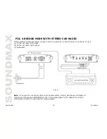
Page 10: ... set it as shown in Fig 4 1 To the car radio left output 2 To the car radio right output 3 Subwoofer Fig 4 Note if you want to use the amplifier in monaural system comply with above illustration to connect and choose the CROSSOVER to LPF The output signals to the subwoofer will be a combination of both the right and left output signals ...

Page 11: ...aker right 5 To the subwoofer Fig 5 Note if you want to use the amplifier in dual mode system connect the speakers as illustrated above and switch the CROSSOVER to OFF The output signals to the amplifier will be stereo of the right and left output signals and the subwoofer will be a combination of both the right and left output signals ...

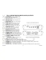
Page 12: ...e level RCA output from the left channel of the unit 9 OUTPUT R accepts the line level RCA output from the right channel of the unit 10 POWER GND to a metal point of the car 11 REMOTE connect the remote input terminal 12 B 12V connect the 12V power supply of car battery Notes on the power supply 13 POWER GREEN illuminates green when unit is on PROTECTOR RED led will turn to red when the unit runs ...

Page 13: ... Distorted audio Low turn on voltage Refer to head unit owner s manual Audio level low Mute circuits is on head unit Check electrical system for low voltage Check ground connection Audio lacks Speakers wired with wrong polarity causing cancellation of bass frequencies Check polarity of wires from amplifiers to each speak as defined by the system design Check battery voltage at amplifier during ope...

Page 14: ... 1 kHz Signal to Noise Ratio 98dB IHF A weighting Input sensitivity LOW LEVEL INPUT 0 3 6V Low pass filter 30 250 Hz 12 dB per octave High pass filter 30 5kHz 12 dB per octave Bass boost 0 12 dB at 50 Hz Power supply 12V Negative Ground Current 30A Dimensions WxHxL 350 x 125 x 315 mm Weight 2 6 Kgs NOTE Specifications design subject to change without notice for improvement The pictures have been d...

Page 15: ...SOUNDMAX SM SA6021 15 2 15 16 16 18 19 20 2 21 3 22 4 23 5 24 6 25 26 27 ...

Page 16: ...SOUNDMAX SM SA6021 16 A MOSFET PWM 12 0 12 50 RCA 5 8 2 ...

Page 17: ...SOUNDMAX SM SA6021 17 0 5 12 1 5 2 12 100 130 ...

Page 18: ...SOUNDMAX SM SA6021 18 4 3 5 3 0 1 ...

Page 19: ...SOUNDMAX SM SA6021 19 8 2 8 2 12B 40 50 0 75 2 2 4 12 ...

Page 20: ...SOUNDMAX SM SA6021 20 5 6 1 LPF 3 1 HPL 2 2 Bass Boost 4 ...

Page 21: ...SOUNDMAX SM SA6021 21 2 1 12V 2 3 4 5 6 remote 2 ...

Page 22: ...SOUNDMAX SM SA6021 22 3 3 1 c 2 c 3 4 3 CROSSOVER OFF ...

Page 23: ...SOUNDMAX SM SA6021 23 4 4 1 c 2 c 3 4 CROSSOVER LPF ...

Page 24: ...SOUNDMAX SM SA6021 24 5 1 2 3 4 5 5 CROSSOVER OFF ...

Page 25: ...OFF LPF 2 HPF 30 5 3 LPF 30 250 4 BASS BOOST 50 0 12 5 LEVEL 6 INPUT L RCA 7 INPUT R RCA 8 OUTPUT L RCA 9 OUTPUT R RCA 10 POWER GND 11 REMOTE 12 B 12V 12V 13 POWER GREEN PROTECTOR RED 14 FUSE 1 15 FUSE 2 16 OUTPUT L 17 OUTPUT L 18 OUTPUT R 19 OUTPUT R ...

Page 26: ...SOUNDMAX SM SA6021 26 RCA RCA ...

Page 27: ...SOUNDMAX SM SA6021 27 SM SA6021 4 10 60 x 2 4 250 4 8 22 3 1 0 05 1 k 98 IHF A weighting 0 3 6 30 250 12 30 5 12 0 12 50 12 30A 350 x 125 x 315 2 6 ...

Reviews: