background image

4

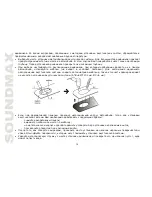
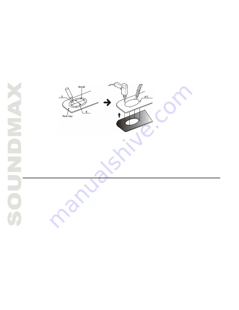
If it will be necessary to cut steel, reinstall the cosmetic panel in place and use the hole you have previously
cut as a template. This will help you ensure proper cutting and a good fit. Now, mark the locations for the
speakers mounting screws, remove the panel and drill the screw holes. When finished, you may replace the

panel.

After cutting and drilling all holes, inspect the mounting areas for any metal burrs or rough edges. File any
area that may interfere with the mounting of the speaker.
Clean any metal shavings from the mounting area and check for areas in which water may enter the speaker

cavity.  Treat the area for water protection when necessary.

Securing the speakers

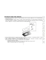
Position the speaker into the mounting hole and re-confirm the correct mounting location and hole placement.

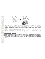
Screw clips are provided to ensure a snug fit. These should be placed over the metal surface and line up the
hole you have previously drilled with the screw clip. Place the speaker into the hole, align the holes and
proceed  to  insert  the  screws.  Be  sure  to  tighten  the  screws  evenly  so  that  they  will  not  warp  the  speaker
frame.

Summary of Contents for SM-CSM694

Page 1: ...SM CSM694 16 24 CM 4 WAY COAXIAL ACOUSTIC SYSTEM Instruction manual 16 X 24 4...

Page 2: ...may be subjected to excessive heat moisture dust or where they will be kicked repeatedly brushed or bumped Before mounting and connecting the wires be sure that wire of the negative pole terminal is...

Page 3: ...t your car dealer or your nearest dealer before mounting CAUTION Take extreme caution when working near the gas tank gas lines brake or hydraulic lines and electrical wiring Mounting the speakers Inst...

Page 4: ...fere with the mounting of the speaker Clean any metal shavings from the mounting area and check for areas in which water may enter the speaker cavity Treat the area for water protection when necessary...

Page 5: ...esire After installation of the acoustic system and having tested it the speaker grill will have to be inserted Turn on you system and follow these steps carefully locate the speaker grill now careful...

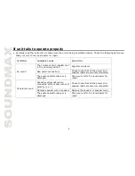
Page 6: ...Bad power connections Check to see that all the power and speaker leads are securely connected No sound The audio cassette receiver is damaged Take your unit to the local dealer for repair Acoustic sy...

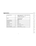
Page 7: ...r 15 20 mm piezo tweeter Magnet main ferrite 30 Oz midrange ferrite tweeter ferrite Peak output power 240 W Rated output power 120 W Impedance 4 hm Sensitivity 92 dB Frequency response 30 22000 Hz Dim...

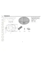
Page 8: ...8 3 x 8 8 2 3 8 8...

Page 9: ...9...

Page 10: ...10 220 151 5...

Page 11: ...11...

Page 12: ...12...

Page 13: ...13 16 24 6 x 9 5 8 2 3 15 20 30 850 240 120 4 92 30 22000 263 5 x 183 x 114 2 1 4 6 x x 360 297 137...

Reviews: